|
9:1 VOLTAGE UNUN.
Version 3
1:9 voltage unun using a FT140-43
Ferrite Toroid Core for 1.0MHz to 60MHz.
For
use with a quick and easy multi-band antenna deployment for portable
and camping operations a simple long wire antenna with an earth plus
counterpoise arrangement with a 9:1
voltage unun is popular.
Requiring
a unun to feed a long wire antenna mostly with a tuner a 9:1
voltage unun
design using a FT140-43
ferrite toroid core was selected.
The
1:9 unun is connect to an un-balanced feed line and to an
un-balanced antenna with an impedance step up from typically 50ohms
to 450ohms, the 1:9 Voltage unun
is design using a FT140-43
Ferrite Toroid Core. It is recommended that a chocking balun be
included for un-balanced
feed line connection.
Similar
to the version 2 unun the new version has achieved much improved
transformation efficiency over a greater band-width. The improved
transformation efficiency over a greater band-width is primarily due
the the evenly spaced windings around the core.
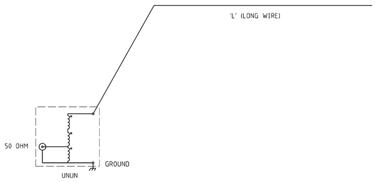
Figure
1 Typical
9:1 voltage
unun and long wire antenna configuration.
Construction
The
1:9 voltage balun has 5 turns wound evenly spaced around the FT140-43
Ferrite Toroid Core. The attention to evenly spaced winding
significantly improved the efficiency and bandwidth of this balun
compared with the version 1 unun.
The
toroidal core was wrapped in overlapping layers of PVC electrical
tape to
protect the enamelled copper wire from insulation puncture from
abrasion with the toroid core and to prevent the windings from
slipping so as to maintain the winding spacing.
The
length of enamelled copper wire per winding for the FT140-43
ferrite toroid core is
determined by length per winding plus tails =
350mm
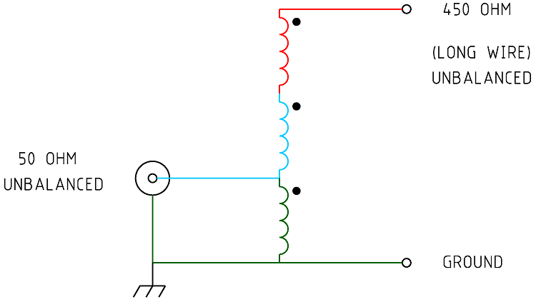
Figure
2 Schematic of the 9:1 voltage
unun.
Typically unbalanced = 50/75 ohms too unbalanced = 450/675 ohms.

Figure
3 Wiring of the 9:1 voltage
unun.
|
Type
|
UnUn
Voltage
|
|
Ratio
|
1:9
|
|
Frequency
Range
|
1.0
~ 60MHz
|
|
Core
Used
|
FT140-43 Ferrite Toroid Core
|
|
Number
of turns
|
5
x 3 Evenly spaced.
|
|
SWR
|
Low
1:1.06 (5.1MHz) High
1:1.7 (60.0MHz)
|
|
PEP
Power Handling.
|
Approximately
100W
|

Photo
1 Completed core
winding assembly. note fibre glass tube sections to hold winding
groups together.

Figure
3
SWR. The AIM
4170C antenna analyser graph
viewing a 450ohm resistive load through the voltage
balun from 0.1MHz to 60MHz. Note the 450ohm resistor appears as 50ohms
due to the 1:9 unun ratio resulting in an ideal SWR of 1:1. The
SWR is shown to be consistently low for all Amateur radio bands with a
high of just overt 1:1.65 for the 6m band.

Figure
4 The AIM
4170C antenna analyser graph
viewing a 450ohm resistive load through the voltage
balun from 0.1MHz to 60MHz. Note the 450ohm resistor should ideally
appears as 50ohms due to the 1:9 balun ratio.

Figure
5 The
AIM
4170C antenna analyser graph
viewing a 450ohm resistive load through the voltage
balun from 0.1MHz to 60MHz. Note the 450ohm resistor should ideally
appears as 50ohms due to the 1:9 balun ratio. The impedance should
ideally be R (Resistance) at 50 ohms and X (Reactance) near zero
ohms. The Purple line shows the resistance component in ohms of the
Impedance and the Orange line shows the reactive component in ohms
of the Impedance, the + values for the reactance represent Inductive
reactance and the negative values represent the Capacitive
reactance.
Conclusion
The
Version 2 1:9 voltage unun using
a FT140-43
Ferrite Toroid Core represents a very efficient balun for a
frequency range from 0.5MHz to 60MHz at a power level of 100W PEP.
Power
Handling
For
Summary of suitable ferrite cores and core types for a frequency range
of 100 kHz to 50 MHz for power levels of 50W, 100W, and 500W
continuous and SSB. It assumes good thermal management and proper
balun design. See: Power
- Ferrite Core Design
Also
see other baluns and ununs:
BALUN
1:1 CHOKE & 1:4 BALUN HF
ladder feed-line to coaxial cable combination choke and 1:4 balun.
(0.1MHz - 30MHz).
BALUN 1:1
CHOKING Choking balun for
lower HF and MF bands. (200kHz - 10MHz).
CHOKING
1:1 BALUN - HF BANDS Reisert choking balun.
(1.0MHz - 30MHz). FT240-43 Ferrite Toroid Core.
CHOKING
1:1 BALUN - HF BANDS Reisert choking balun (1.5MHz - 30MHz). FT140-43
Ferrite Toroid Core.
CHOKING
1:1 BALUN - LOW VHF BAND Choking balun.
(10MHz - 60MHz). FT140-43 Ferrite Toroid Core.
BALUN
1:1 CURRENT 1:1 Guanella Current balun using a L15
ferrite core (1.8 - 30MHz).
BALUN
1:4 CURRENT 1:4 Guanella Current balun using a L15
ferrite core (1.8 - 30MHz).
BALUN
1:4 SINGLE CORE CURRENT 1:4 Guanella Current Balun, single FT240-43
ferrite toroid cores. (0.3MHz - 30MHz).
BALUN 1:1
VOLTAGE 1:1 Ruthroff voltage balun using a T-200-2 powdered iron
toroid core (1.8 - 30MHz).
BALUN 4:1
VOLTAGE 4:1 Ruthroff voltage balun using a T-200-2 powdered iron
toroid core (1.8 - 30MHz).
BALUN 6:1
VOLTAGE - VERSION 1 6:1 Voltage balun using a L15 ferrite toroid core (1.8 - 30MHz).
BALUN 6:1
VOLTAGE - VERSION 2 6:1 Voltage balun using a FT140-43 Ferrite
Toroid Core (1.8 - 30MHz)
BALUN 9:1
VOLTAGE - VERSION 1 9:1 Voltage balun using a L15 ferrite toroid core (1.8 - 30MHz).
BALUN 9:1
VOLTAGE - VERSION 2 9:1 Voltage balun using a FT140-43 Ferrite
Toroid Core (0.5 - 60MHz).
UNUN 9:1
VOLTAGE 9:1 voltage unun
using a T-200-2 powdered iron toroid core (1.8 - 30MHz).
UNUN 9:1
VOLTAGE VERSION 2 9:1 voltage unun using a L15 ferrite core (1.8
- 30MHz).
UNUN 9:1
VOLTAGE VERSION 3 9:1 voltage unun using a FT140-43 ferrite core
(0.5 - 60MHz).
TOP
OF PAGE
Page
last revised 12 March 2022
|