|
1:1 VOLTAGE BALUN
1:1 Ruthroff voltage balun. Install July 2012.
Requiring
a balun to feed a balanced feed line with an un-balanced T-Match
network a 1:1 Ruthroff voltage balun design using a T200-2
Toroid core was selected. While the 4:1 ratio is often referred to
for the interface between T-Match
network and a balanced antenna system it will often not be the ideal
choice when very low impedances are encountered. It is for this reason
that I chose to not include the balun as an integral feature of the
T-Match network, opting for the flexibility of an outboard balun and
the ability to trial various baluns subject to the antenna system and
impedances presented.
Construction
The
T-200-2 powdered iron toroid core
was tightly rapped in a lay of overlapping PVC electrical tape to
prevent the enamelled copper wire's insulation being damaged
during winding and to offer some additional electrical insulation with
core.
The
triple bifilar winding of 17 turns are wound evenly spaced around the
toroid core with the two individual windings wound close together.
The
length of enamelled copper wire per winding for the T-200-2 powdered
iron toroid core
is determined by length per winder = 50mm per turn plus 200mm
tails
The
exact number of turns is not critical but the numbers listed in the
preceding table should yield good results. It is possible to exceed
the power ratings listed above but the performance of the balun may be
degraded during high SWR causing heating of the core.

Figure
1 Schematic of the 1:1 Ruthroff voltage
balun. Typically
unbalanced = 50/75 ohms and balanced = 50/75 ohms.

Figure
2 Wiring of the 1:1 Ruthroff voltage balun.
Note
this drawing shows winding connections and not the number of turns
required. See table
|
TOROID
|
NUMBER
OF TURNS
|
POWER
RATING
|
|
T80-2
|
25
|
60
Watts
|
|
T106-2
|
16
|
100
Watts
|
|
T130-2
|
18
|
150
Watts
|
|
T157-2
|
16
|
250
Watts
|
|
T200-2
|
17
|
400
Watts
|
|
T200A-2
|
13
|
400
Watts
|
|
T400-2
|
14
|
1000
Watts
|
Table
1 lists alternative toroid core with winding suggestions.
Parts
list.
-
T-200-2
powdered iron toroid core from Amidon
-
About
600mm of 1.25mm Enamelled copper wire.
-
Two
black binding posts
-
SO-239
UHF chassis mount connector
-
Sealed Polycarbonate Enclosures 82 x 80 x 55mm
from Jaycar. See
Fig 3 for details
Figure 3 Sealed Polycarbonate Enclosures 82 x 80 x 55mm
details
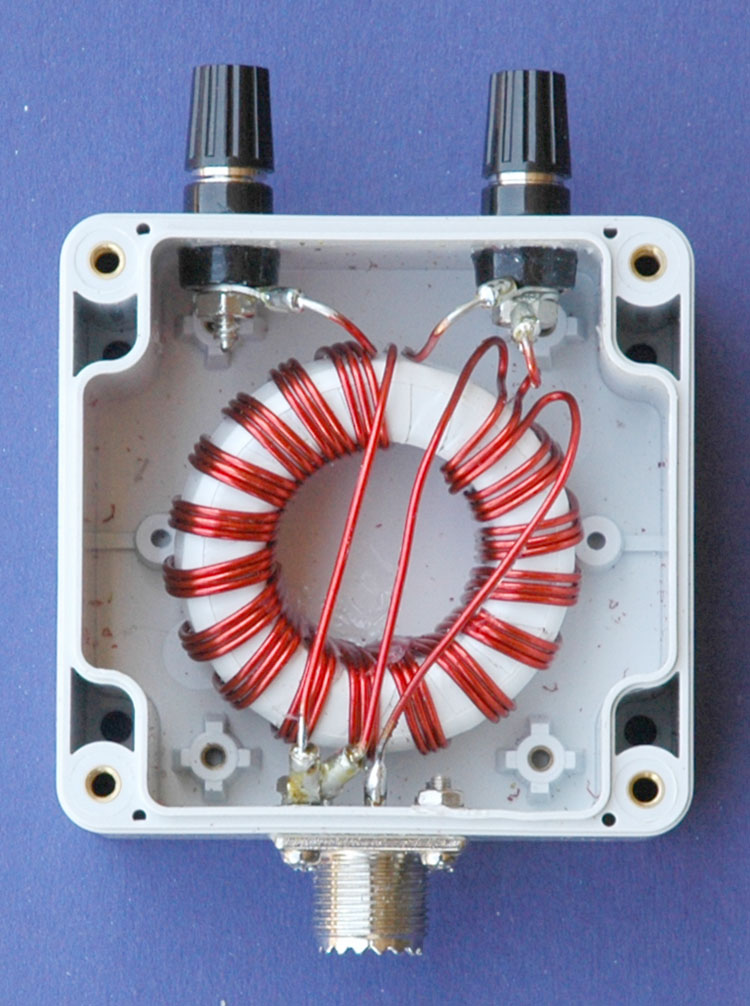
Photo 1
1:1 Ruthroff voltage balun
assembled.
The
evaluation of the efficiency of the balun over the desired bandwidth
(1.8 - 30MHz) was carried out by testing the impedance that could be
seen from unbalanced
side to a resistive load applied to the balanced side using an
antenna analyser. The efficiency is shown to cut of sharply below
1.8MHz and gradually taper of above about 40MHz. The below antenna
analyser plot viewing a 100ohm resistive load attached to the
balanced side of the balun and measured at a nominal impedance of
50ohms presented as anticipated an approximate 100ohm load to the
analyser and produced about a 2:1 SWR. Despite not having carried
out this test previously the results are more or less what was
expected and demonstrates that the balun's 1:1 voltage
transformation occurs efficiently from 1.8 to well above 30MHz.
Figure
4
AIM
4170C antenna analyser plot viewing a 100ohm resistive load through
the Ruthroff voltage balun. Note the 100ohm resistor appears as
100ohms due to the 1:1 balun ratio resulting in an ideal SWR of 2:1.
(1) = 1.8MHz & (2) = 30.MHz.
AIM 4170C antenna analyser explanation;
|
SWR
|
Standing Wave Ratio.
|
|
Zmag
|
Total Impedance.
|
|
Rs
|
Resistive component of the total impedance
|
|
Xs
|
Reactive component of the total impedance also indicating the +/-sign
of the value. Inductive being a positive value and capacitive
being a negative number.
|
|
Theta
|
Phase angle between voltage and current.
|
|
Return Loss
|
Total reflected system loss.
|
An additional evaluation of the efficiency of the balun was preformed by
simply measuring the RF power at selected frequencies fed into the
balun and measuring the out put power from the balun using the set up
shown in Figure 7.
For example, RF was applied to the input of the Balun at a frequency
of 1.8 MHz at a power of 5 Watts with 4 Watts being measured at the
output meter. The below formula was applied revealing a Balun loss of
0.97dB at this frequency.

Figure 5 shows the results of measurements taken at various
frequencies including the calculated loss. Figure 6 shows the graphed
results of the losses verses frequency.
Concussion of this evaluation is that the efficiency between 3.5 MHz
to 14 MHz is very high as to be unnoticeable and that even at 28 MHz the loss would represent only about half an ‘S’ point.
The limitation of this evaluation is that it is under an ideal situation
of 50 ohms and that more extreme loads will likely show greater
losses.
|
Frequencies
|
Input
PWR
|
Output
PWR
|
dB
Loss
|
|
1,60
|
5,00
|
3,80
|
-1,2
|
|
1,80
|
5,00
|
4,00
|
-1,0
|
|
3,60
|
5,00
|
4,80
|
-0,2
|
|
7,10
|
5,00
|
4,95
|
0,0
|
|
10,10
|
5,00
|
4,80
|
-0,2
|
|
14,50
|
5,00
|
4,50
|
-0,5
|
|
21,10
|
5,00
|
3,95
|
-1,0
|
|
28,10
|
5,00
|
3,50
|
-1,5
|
|
29,70
|
5,00
|
3,45
|
-1,6
|
Figure
5
Table of test results.
Figure
6
Plot of Balun losses verses frequency.
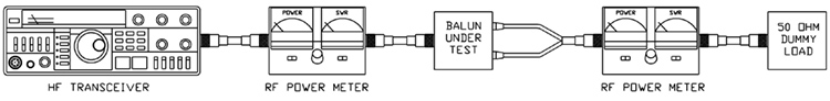
Figure
7
Efficiency evaluation set up.
Also
see other baluns and ununs:
BALUN
1:1 CHOKE & 1:4 BALUN
HF
ladder feed-line to coaxial cable combination choke and 1:4 balun.
(0.1MHz - 30MHz).
BALUN
1:1 CHOKING
Choking balun
for lower HF and MF bands.
(200kHz - 10MHz).
CHOKING
1:1 BALUN - HF BANDS Reisert
choking balun.
(1.0MHz - 30MHz). FT240-43 Ferrite Toroid Core.
CHOKING
1:1 BALUN - HF BANDS Reisert
choking balun
(1.5MHz - 30MHz). FT140-43 Ferrite Toroid Core.
CHOKING
1:1 BALUN - LOW VHF BAND
Choking balun.
(10MHz - 60MHz). FT140-43 Ferrite Toroid Core.
BALUN
1:1 CURRENT 1:1 Guanella
Current balun using
a L15 ferrite core (1.8
- 30MHz).
BALUN
1:4 CURRENT 1:4 Guanella
Current balun using
a L15 ferrite core (1.8
- 30MHz).
BALUN
1:4 SINGLE CORE CURRENT
1:4 Guanella
Current Balun, single FT240-43
ferrite toroid cores. (0.3MHz
- 30MHz).
BALUN
1:1 VOLTAGE 1:1 Ruthroff
voltage balun using
a T-200-2 powdered iron toroid
core (1.8 - 30MHz).
BALUN
4:1 VOLTAGE 4:1 Ruthroff
voltage balun using
a T-200-2 powdered iron toroid
core (1.8 - 30MHz).
BALUN
6:1 VOLTAGE - VERSION 1
6:1 Voltage balun using
a L15 ferrite toroid
core (1.8 - 30MHz).
BALUN
6:1 VOLTAGE - VERSION 2
6:1 Voltage balun using
a FT140-43 Ferrite Toroid
Core (1.8 - 30MHz)
BALUN
9:1 VOLTAGE - VERSION 1
9:1 Voltage balun using
a L15 ferrite toroid
core (1.8 - 30MHz).
BALUN
9:1 VOLTAGE - VERSION 2
9:1 Voltage balun using
a FT140-43 Ferrite Toroid
Core (0.5 - 60MHz).
UNUN
9:1 VOLTAGE 9:1
voltage unun
using a T-200-2
powdered iron toroid
core (1.8 - 30MHz).
UNUN
9:1 VOLTAGE VERSION 2 9:1
voltage unun
using a L15 ferrite core (1.8
- 30MHz).
UNUN
9:1 VOLTAGE VERSION 3 9:1
voltage unun
using a FT140-43 ferrite core
(0.5 - 60MHz).
TOP
OF PAGE
Page
last revised 12 March 2022
|