|
1:4 GUANELLA
CURRENT BALUN
1:4 Guan
Ella Current Balun.
Requiring
a balun to feed a balanced feed line from an un-balanced T-Match
tuner, a 1:4 Guanella Current
balun design using two L15
ferrite toroid cores was selected among other balun types.
An impedance transformation
balun may be required due the variations in impedances often encounter with
multi-band balanced antenna system. The balun may be required to
sep up or down the feed impedance presented at the T-Match tuner to
improve the matching range, it
is for this reason that I chose to not include the balun as an
integral feature of the T-Match tuner, opting for the flexibility of
an outboard balun and the ability to trial various baluns subject to
the antenna system and impedances presented.
The
Guanella Current
balun is a low loss, broadband balun that will ideally choke off common mode
currents entering the radio room and importantly provide a
transition from the un-balanced output of the T-Match tuner to the
balanced antenna system feed line.
While
using the balun to choke off common mode currents is best achieved at
the antenna end of the feed line, this is not a practical arrangement
for a balanced feed line system.
Construction
The
1:4 current balun is derived from two 1:1 current baluns with each consisting
of a close double bifilar winding of
8 turns wound evenly
spaced around the L15
ferrite toroid core. The toroidal cores are rapped in an overlapping layer pink
heavy duty Teflon plumbers tape to protect the enamelled copper
wire from insulation puncture from abrasion with the toroid core.
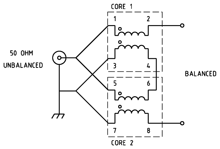
Figure 1 Schematic of the 1:4 Guanella Current
balun.

Figure 2 Wiring of the 1:4 Guanella Current
balun.
Note
this drawing shows winding connections and not the number of turns
required. See article for details.
Parts
list.
-
2
x L15
ferrite toroid core. Jaycar
Cat.
No. LO-1238
-
Pink
heavy duty Teflon plumbers tape.
-
About 2
x 600mm of 1.25mm Enamelled copper wire.
-
Two
Gold
Banana Socket Binding Post - Black. Jaycar
Cat.
No. PT-0431
-
SO-239
UHF chassis mount connector
-
Sealed Polycarbonate Enclosures 82 x 80 x 55mm
from Jaycar Cat.
No. HB-6230. See
Fig 3 for details
Figure 3 Sealed Polycarbonate Enclosures 82 x 80 x 55mm
details. Designed
to IP65 of IEC 529 and NEMA 4

Photo
1 1:4
Guanella current balun individual core windings assembled.

Photo
2 1:4
Guanella current balun individual core windings stack
assembled.

Photo
3
1:4
Guanella current balun assembled.
The
evaluation of the efficiency of the balun over the desired bandwidth
(1.8 - 30MHz) was carried out by testing the impedance that could be
seen from unbalanced
side to a resistive load applied to the balanced side using an
antenna analyser. The efficiency is shown to be relatively flat from
below 1.8MHz to above 30MHz. The below antenna analyser plot viewing
a 200ohm resistive load attached to the balanced side of the balun
and measured at a nominal impedance of 50ohms presented as
anticipated an approximate 50ohm load to the analyser and ideally
produced about a 1:1 SWR. The results are more or less what was
expected and demonstrates that the balun's 1:4 current
transformation occurs efficiently from well below 1.8 to well above
30MHz.

Figure
4 AIM
4170C antenna analyser plot viewing a 200ohm resistive load through
the Guanella current balun. Note the 200ohm resistor appears as 50ohms
due to the 1:4 balun ratio resulting in an ideal SWR of 1:1. This
plot shows an SWR of almost exactly 1:1 with no reactance at a
frequency of 500kHz with consistent flat SWR throughout the HF
spectrum with almost no obvious reactance at 30MHz.

Figure
5 AIM
4170C antenna analyser plot viewing a 100ohm resistive load through
the Guanella current balun. Note the 100ohm resistor appears as 25ohms
due to the 1:4 balun ratio resulting in an ideal SWR of 2:1. This
plot shows an SWR of approximately 2:1 from 500kHz through to 30MHz
and with modest inductive reactance towards the upper frequencies.

Figure
6 AIM
4170C antenna analyser plot viewing a 450ohm resistive load through
the Guanella current balun. Note the 450ohm resistor appears as
112ohms due to the 1:4 balun ratio resulting in an ideal SWR of 2.2:1. This
plot shows an SWR of approximately 2.5:1 at 500kHz through to 30MHz
and with significant capacitive reactance towards the mid and upper
frequencies.
AIM 4170C antenna analyser explanation;
|
SWR
|
Standing Wave Ratio.
|
|
Zmag
|
Total Impedance.
|
|
Rs
|
Resistive component of the total impedance
|
|
Theta
|
Phase angle between voltage and current.
+ indicates inductive reactance while - indicates capacitive
reactance.
|
Power
Handling
For
Summary of suitable ferrite cores and core types for a frequency range
of 100 kHz to 50 MHz for power levels of 50W, 100W, and 500W
continuous and SSB. It assumes good thermal management and proper
balun design. See: Power
- Ferrite Core Design
Also
see other baluns and ununs:
BALUN
1:1 CHOKE & 1:4 BALUN HF
ladder feed-line to coaxial cable combination choke and 1:4 balun.
(0.1MHz - 30MHz).
BALUN 1:1
CHOKING Choking balun for
lower HF and MF bands. (200kHz - 10MHz).
CHOKING
1:1 BALUN - HF BANDS Reisert choking balun.
(1.0MHz - 30MHz). FT240-43 Ferrite Toroid Core.
CHOKING
1:1 BALUN - HF BANDS Reisert choking balun (1.5MHz - 30MHz). FT140-43
Ferrite Toroid Core.
CHOKING
1:1 BALUN - LOW VHF BAND Choking balun.
(10MHz - 60MHz). FT140-43 Ferrite Toroid Core.
BALUN
1:1 CURRENT 1:1 Guanella Current balun using a L15
ferrite core (1.8 - 30MHz).
BALUN
1:4 CURRENT 1:4 Guanella Current balun using a L15
ferrite core (1.8 - 30MHz).
BALUN
1:4 SINGLE CORE CURRENT 1:4 Guanella Current Balun, single FT240-43
ferrite toroid cores. (0.3MHz - 30MHz).
BALUN 1:1
VOLTAGE 1:1 Ruthroff voltage balun using a T-200-2 powdered iron
toroid core (1.8 - 30MHz).
BALUN 4:1
VOLTAGE 4:1 Ruthroff voltage balun using a T-200-2 powdered iron
toroid core (1.8 - 30MHz).
BALUN 6:1
VOLTAGE - VERSION 1 6:1 Voltage balun using a L15 ferrite toroid core (1.8 - 30MHz).
BALUN 6:1
VOLTAGE - VERSION 2 6:1 Voltage balun using a FT140-43 Ferrite
Toroid Core (1.8 - 30MHz)
BALUN 9:1
VOLTAGE - VERSION 1 9:1 Voltage balun using a L15 ferrite toroid core (1.8 - 30MHz).
BALUN 9:1
VOLTAGE - VERSION 2 9:1 Voltage balun using a FT140-43 Ferrite
Toroid Core (0.5 - 60MHz).
UNUN 9:1
VOLTAGE 9:1 voltage unun
using a T-200-2 powdered iron toroid core (1.8 - 30MHz).
UNUN 9:1
VOLTAGE VERSION 2 9:1 voltage unun using a L15 ferrite core (1.8
- 30MHz).
UNUN 9:1
VOLTAGE VERSION 3 9:1 voltage unun using a FT140-43 ferrite core
(0.5 - 60MHz).
TOP
OF PAGE
Page
last revised 12 March 2022
|