|
9:1 VOLTAGE BALUN
9:1 Voltage balun. Install
November 2016.
Requiring
a balun to feed a balanced antenna from an un-balanced load with an
impedance step up from 50ohms to 450ohms, a 1:9 Voltage
balun design using an L15 ferrite toroid cores was selected.
Construction
The
1:9 voltage balun has 5 turns wound evenly spaced around the L15
ferrite toroid core with the five individual windings wound
close together. The toroidal core was wrapped in an overlapping
layer pink
heavy duty Teflon plumbers tape to protect the enamelled
copper wire from insulation puncture from abrasion with the toroid
core.
As
this Balun will be used out in the weather a weatherproof plastic
enclosure is used. See photos 1,2 and 3.
The
entry holes for the SO-239 connector and the binding
post have small bead of rubberised silicon sealant to achieve full
waterproofing of the Balun. Photo
2 shows the perfect application of the rubberised
silicon sealant spread uniformly from under the binding post, which
will also give additional grip if the post were over tightened.
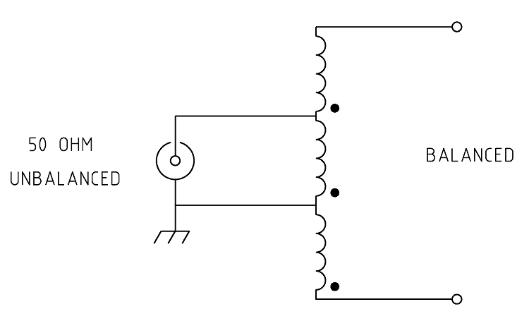
Figure 1 Schematic of the 1:9 Voltage balun
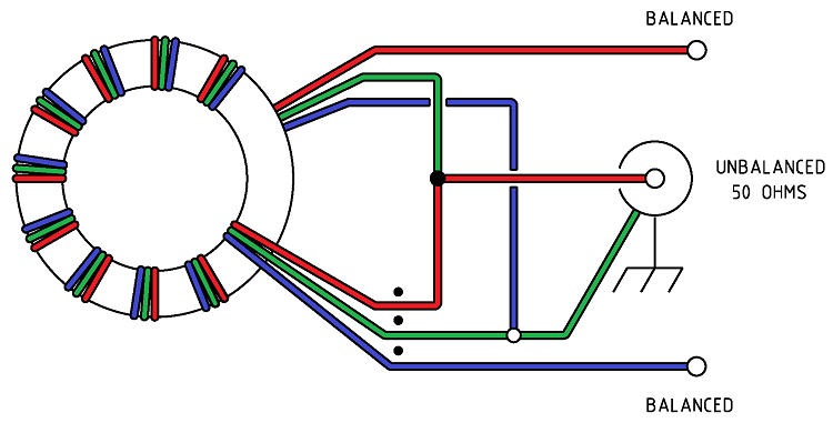
Figure
2 Wiring of the 1:9 Voltage balun.
Note
this drawing shows winding connections and not the number of turns
required. See article for details.
Parts
list.
-
1.25mm
Enamelled copper wire.
-
L15
ferrite toroid core. Jaycar
Cat. No. LO-1238
-
Pink
heavy duty Teflon plumbers tape.
-
About
3 x 500mm of 1.25mm Enamelled copper wire.
-
Two
Gold
Banana Socket Binding Post - Black. Jaycar
Cat. No. PT-0431
-
SO-239
UHF chassis mount connector
-
Sealed
Polycarbonate Enclosures 82 x 80 x 55mm from Jaycar
Cat.
No. HB-6230

Photo 1 1:9 Voltage balun
enclosure assembled.
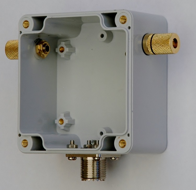
Photo 2 1:9 Voltage balun
enclosure
assembled.

Photo 3 1:9 Voltage balun
assembled in weatherproof enclosure.
The
evaluation of the efficiency of the balun over the desired bandwidth
(1.0 - 30MHz) was carried out by testing the impedance that could be
seen from unbalanced side to a resistive load applied to the
balanced side using an antenna analyser. The below antenna analyser
plot views a 450ohm resistive load attached to the balanced side of
the balun and measured at a nominal impedance of 50ohms presented as
anticipated an approximate 50ohm load to the analyser and produced
about a 1:1 SWR.
The
performance of the balun from 1.0MHz to about 30MHz is good and
shows little reactance, there is however a gradual rise in
reactance above 30MHz along with a gradual rise in the SWR. Despite
this rise in reactance and SWR the balun should still perform well
up into the 50MHz amateur band.

Figure
3 AIM
4170C antenna analyser plot viewing a 450ohm resistive load through
the voltage balun. Note the 450ohm resistor appears as 50ohms due to
the 9:1 balun ratio resulting in an ideal SWR of 1:1.
AIM 4170C antenna analyser explanation;
|
SWR
|
Standing Wave Ratio.
|
|
Zmag
|
Total Impedance.
|
|
Theta
|
Phase angle between voltage and current.
|
Power
Handling
For
Summary of suitable ferrite cores and core types for a frequency range
of 100 kHz to 50 MHz for power levels of 50W, 100W, and 500W
continuous and SSB. It assumes good thermal management and proper
balun design. See: Power
- Ferrite Core Design
Also
see other baluns and ununs:
BALUN
1:1 CHOKE & 1:4 BALUN HF
ladder feed-line to coaxial cable combination choke and 1:4 balun.
(0.1MHz - 30MHz).
BALUN 1:1
CHOKING Choking balun for
lower HF and MF bands. (200kHz - 10MHz).
CHOKING
1:1 BALUN - HF BANDS Reisert choking balun.
(1.0MHz - 30MHz). FT240-43 Ferrite Toroid Core.
CHOKING
1:1 BALUN - HF BANDS Reisert choking balun (1.5MHz - 30MHz). FT140-43
Ferrite Toroid Core.
CHOKING
1:1 BALUN - LOW VHF BAND Choking balun.
(10MHz - 60MHz). FT140-43 Ferrite Toroid Core.
BALUN
1:1 CURRENT 1:1 Guanella Current balun using a L15
ferrite core (1.8 - 30MHz).
BALUN
1:4 CURRENT 1:4 Guanella Current balun using a L15
ferrite core (1.8 - 30MHz).
BALUN
1:4 SINGLE CORE CURRENT 1:4 Guanella Current Balun, single FT240-43
ferrite toroid cores. (0.3MHz - 30MHz).
BALUN 1:1
VOLTAGE 1:1 Ruthroff voltage balun using a T-200-2 powdered iron
toroid core (1.8 - 30MHz).
BALUN 4:1
VOLTAGE 4:1 Ruthroff voltage balun using a T-200-2 powdered iron
toroid core (1.8 - 30MHz).
BALUN 6:1
VOLTAGE - VERSION 1 6:1 Voltage balun using a L15 ferrite toroid core (1.8 - 30MHz).
BALUN 6:1
VOLTAGE - VERSION 2 6:1 Voltage balun using a FT140-43 Ferrite
Toroid Core (1.8 - 30MHz)
BALUN 9:1
VOLTAGE - VERSION 1 9:1 Voltage balun using a L15 ferrite toroid core (1.8 - 30MHz).
BALUN 9:1
VOLTAGE - VERSION 2 9:1 Voltage balun using a FT140-43 Ferrite
Toroid Core (0.5 - 60MHz).
UNUN 9:1
VOLTAGE 9:1 voltage unun
using a T-200-2 powdered iron toroid core (1.8 - 30MHz).
UNUN 9:1
VOLTAGE VERSION 2 9:1 voltage unun using a L15 ferrite core (1.8
- 30MHz).
UNUN 9:1
VOLTAGE VERSION 3 9:1 voltage unun using a FT140-43 ferrite core
(0.5 - 60MHz).
TOP
OF PAGE
Page
last revised 27 January, 2026
|