|
1:4 GUANELLA
CURRENT BALUN - HF
1:4 Guanella
Current Balun for HF and MF bands. (0.3MHz - 30MHz).
Requiring a balun to feed a balanced feed line from an un-balanced T-Match tuner, a 1:4 Guanella Current balun design using a single FT240-43 ferrite toroid core was selected. An impedance transformation balun is required due to variations in impedances that are nearly always on the higher side of the nominal 50 ohms when feeding a multi-band balanced antenna system. The balun may be required to step up the feed impedance presented at the T-Match tuner to improve the matching range.
Construction:
The 1:4 current balun consists of two double bifilar windings of 11.5 turns each, wound evenly spaced around the FT240-43 ferrite toroid core, as shown in figure 2.
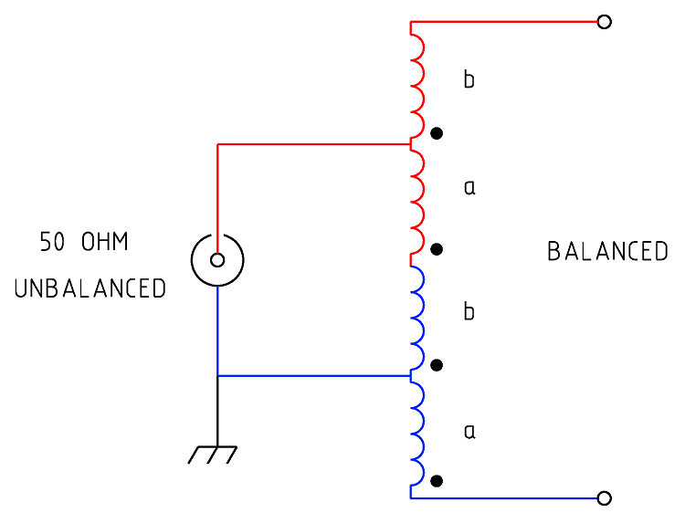
Figure 1 Schematic of the 1:4 Guanella Current
balun.
|
Type
|
Impedance
transformation
|
|
Ratio
|
1:4
|
|
Frequency Range
|
1.5 ~ 30MHz
|
|
Core Used
|
FT240-43 Ferrite
Toroid Core
|
|
Number of turns
|
a = 11.5 tuns plus b =
11.5 turns
|
|
SWR
|
1.2:1 or less. Ref:
Figure 3
|
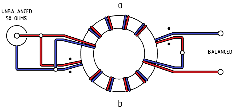
Figure 2 Wiring of the 1:4 Guanella Current
balun.
Note
this drawing shows winding connections and not the number of turns
required. See article for details.
Parts
list.
-
1
x FT240-43 ferrite toroid core.
-
4
x 800mm of PTFE silver plated copper wire, 1.0mm, AWG 18, WHITE
Testing
The AIM 4170C antenna
analyser recorded the impedance transformation efficiency of the balun over a frequency range from 1.0 MHz to 30 MHz.
The evaluation of the balun's efficiency across the desired bandwidth (1.0 - 30 MHz) was conducted by testing the impedance seen from the unbalanced side to a resistive load applied to the balanced side of the balun using an AIM 4170C antenna
analyser. The efficiency was found to be relatively consistent from below 1.0 MHz to above 30 MHz. The antenna
analyser plot below shows a 200-ohm resistive load connected to the balanced side of the balun, with measurements taken at a nominal impedance of 50 ohms. As expected, this
set-up presented an approximate 50-ohm load to the analyser and ideally resulted in a 1:1
SWR. The results are slightly higher than anticipated, but they demonstrate that the balun's 1:4 current transformation occurs reasonably efficiently from well below 1.0 MHz to beyond 30 MHz.

Figure 3
AIM
4170C antenna analyser plot viewing a 200ohm resistive load through
the Guanella current balun. Note the 200ohm resistor appears as
50ohms due to the 1:4 balun ratio resulting in an ideal SWR of 1:1. This
plot shows an SWR ranging from 1.0:1 to about 1.2:1

Figure 4
AIM
4170C antenna analyser plot viewing a 200ohm resistive load through
the Guanella current balun. Note the 200ohm resistor appears as 50ohms
due to the 1:4 balun ratio. The Rs (Resistive load) tracks
closely with Zmag as would be hoped with the Xs (Reactive load) being
relatively low.
Power
Handling
For
Summary of suitable ferrite cores and core types for a frequency range
of 100 kHz to 50 MHz for power levels of 50W, 100W, and 500W
continuous and SSB. It assumes good thermal management and proper
balun design. See: Power
- Ferrite Core Design
BALUN
1:1 CHOKE & 1:4 BALUN HF
ladder feed-line to coaxial cable combination choke and 1:4 balun.
(0.1MHz - 30MHz).
BALUN 1:1
CHOKING Choking balun for
lower HF and MF bands. (200kHz - 10MHz).
CHOKING
1:1 BALUN - HF BANDS Reisert choking balun.
(1.0MHz - 30MHz). FT240-43 Ferrite Toroid Core.
CHOKING
1:1 BALUN - HF BANDS Reisert choking balun (1.5MHz - 30MHz). FT140-43
Ferrite Toroid Core.
CHOKING
1:1 BALUN - LOW VHF BAND Choking balun.
(10MHz - 60MHz). FT140-43 Ferrite Toroid Core.
BALUN
1:1 CURRENT 1:1 Guanella Current balun using a L15
ferrite core (1.8 - 30MHz).
BALUN
1:4 CURRENT 1:4 Guanella Current balun using a L15
ferrite core (1.8 - 30MHz).
BALUN
1:4 SINGLE CORE CURRENT 1:4 Guanella Current Balun, single FT240-43
ferrite toroid cores. (0.3MHz - 30MHz).
BALUN 1:1
VOLTAGE 1:1 Ruthroff voltage balun using a T-200-2 powdered iron
toroid core (1.8 - 30MHz).
BALUN 4:1
VOLTAGE 4:1 Ruthroff voltage balun using a T-200-2 powdered iron
toroid core (1.8 - 30MHz).
BALUN 6:1
VOLTAGE - VERSION 1 6:1 Voltage balun using a L15 ferrite toroid core (1.8 - 30MHz).
BALUN 6:1
VOLTAGE - VERSION 2 6:1 Voltage balun using a FT140-43 Ferrite
Toroid Core (1.8 - 30MHz)
BALUN 9:1
VOLTAGE - VERSION 1 9:1 Voltage balun using a L15 ferrite toroid core (1.8 - 30MHz).
BALUN 9:1
VOLTAGE - VERSION 2 9:1 Voltage balun using a FT140-43 Ferrite
Toroid Core (0.5 - 60MHz).
UNUN 9:1
VOLTAGE 9:1 voltage unun
using a T-200-2 powdered iron toroid core (1.8 - 30MHz).
UNUN 9:1
VOLTAGE VERSION 2 9:1 voltage unun using a L15 ferrite core (1.8
- 30MHz).
UNUN 9:1
VOLTAGE VERSION 3 9:1 voltage unun using a FT140-43 ferrite core
(0.5 - 60MHz).
TOP
OF PAGE
Page
last revised 20 September, 2019
Page
last revised 25
September, 2025
|