|
9:1 VOLTAGE UNUN.
Version 2
9:1 voltage unun using a L15 ferrite core.
With
the view to establish a quick and easy multi-band antenna deployment
for portable and camping operations a simple long wire antenna with an
earth or earth plus counterpoise arrangement with a 9:1 voltage
unun is one possible solution.
Requiring
a unun to feed a long wire antenna ideally without a tuner a 9:1 voltage
unun
design using a L15
ferrite toroid core
was selected.
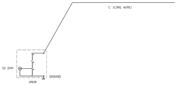
Figure
1 Typical
9:1 voltage
unun and long wire antenna configuration.
Construction
1.25mm Enamelled copper
wire was used in a triple bifilar winding of 4 turns wound evenly spaced around the
L15
ferrite toroid core with the three individual windings wound close together.
The
length of enamelled copper wire per winding for the L15
ferrite toroid core
is determined by length per winding plus tails = 600mm

Figure
2 Schematic of the 9:1 voltage
unun.
Typically unbalanced = 50/75 ohms too unbalanced = 450/675 ohms.
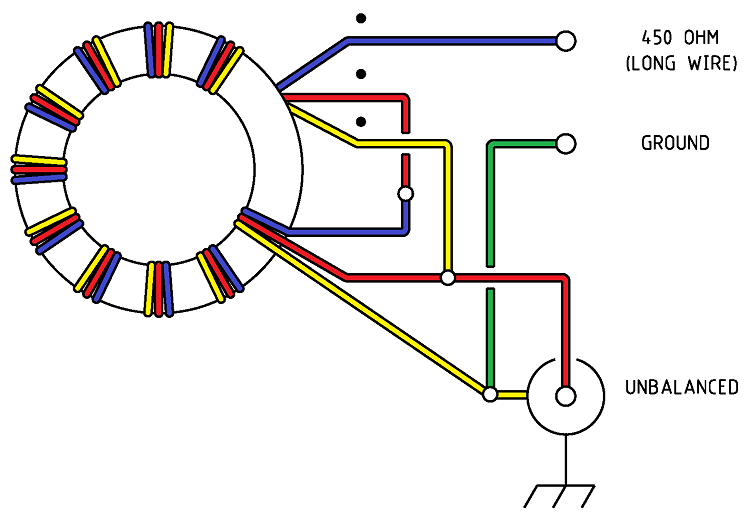
Figure
3 Wiring of the 9:1 voltage
unun.
Note
this drawing shows winding connections and not the number of turns
required. See article for details.
Parts
list.
-
1
x L15
ferrite toroid core. Jaycar
Cat.
No. LO-1238
-
Pink
heavy duty Teflon plumbers tape.
-
About 3
x 400mm of 1.25mm Enamelled copper wire.
-
Black
and Green binding posts.
-
SO-239
UHF chassis mount connector
-
Sealed Polycarbonate Enclosures 82 x 80 x 55mm
from Jaycar Cat.
No. HB-6230. See
Fig 3 for details
Figure 4 Sealed Polycarbonate Enclosures 82 x 80 x 55mm
details

Photo
1 Completed core
winding assembly. note fibre glass tube sections to hold winding
groups together.
The evaluation of the efficiency
of the unun over the desired bandwidth (1.8 - 30MHz) was carried out
by testing the impedance that could be seen from transceiver
side of the unun to a resistive load applied to the
antenna side of the unun using
an antenna analyser.

Figure
5 AIM
4170C antenna analyser plot viewing a 450ohm resistive load through
the unun.
Note the 450ohm resistor appears as 50ohms due to the 9:1
unun
ratio resulting in an ideal SWR of 1:1.

Figure
6 AIM
4170C antenna analyser plot viewing a 100ohm resistive load through
the unun.
Note the 100ohm resistor appears as 11.1ohms due to the 9:1
unun
ratio resulting in an ideal SWR of 4.5:1.

Figure
7 AIM
4170C antenna analyser plot viewing a 1000ohm resistive load through
the unun.
Note the 1000ohm resistor appears as 111ohms due to the 9:1
unun
ratio resulting in an ideal SWR of 2.2:1.
AIM 4170C antenna analyser explanation;
|
SWR
|
Standing Wave Ratio.
|
|
Zmag
|
Total Impedance.
|
|
Theta
|
Phase angle between voltage and current.
|
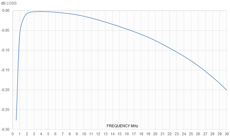
Figure
8 Plot of the Unun
losses verses frequency calculated from the AIM
4170C antenna analyser SWR
data. The graph shows the worst loss figure between 1.0MHz and 30MHz
at -0.2dB at 30MHz, an extraordinarily low figure.
Power
Handling
For
Summary of suitable ferrite cores and core types for a frequency range
of 100 kHz to 50 MHz for power levels of 50W, 100W, and 500W
continuous and SSB. It assumes good thermal management and proper
balun design. See: Power
- Ferrite Core Design
Also
see other baluns and ununs:
BALUN
1:1 CHOKE & 1:4 BALUN HF
ladder feed-line to coaxial cable combination choke and 1:4 balun.
(0.1MHz - 30MHz).
BALUN 1:1
CHOKING Choking balun for
lower HF and MF bands. (200kHz - 10MHz).
CHOKING
1:1 BALUN - HF BANDS Reisert choking balun.
(1.0MHz - 30MHz). FT240-43 Ferrite Toroid Core.
CHOKING
1:1 BALUN - HF BANDS Reisert choking balun (1.5MHz - 30MHz). FT140-43
Ferrite Toroid Core.
CHOKING
1:1 BALUN - LOW VHF BAND Choking balun.
(10MHz - 60MHz). FT140-43 Ferrite Toroid Core.
BALUN
1:1 CURRENT 1:1 Guanella Current balun using a L15
ferrite core (1.8 - 30MHz).
BALUN
1:4 CURRENT 1:4 Guanella Current balun using a L15
ferrite core (1.8 - 30MHz).
BALUN
1:4 SINGLE CORE CURRENT 1:4 Guanella Current Balun, single FT240-43
ferrite toroid cores. (0.3MHz - 30MHz).
BALUN 1:1
VOLTAGE 1:1 Ruthroff voltage balun using a T-200-2 powdered iron
toroid core (1.8 - 30MHz).
BALUN 4:1
VOLTAGE 4:1 Ruthroff voltage balun using a T-200-2 powdered iron
toroid core (1.8 - 30MHz).
BALUN 6:1
VOLTAGE - VERSION 1 6:1 Voltage balun using a L15 ferrite toroid core (1.8 - 30MHz).
BALUN 6:1
VOLTAGE - VERSION 2 6:1 Voltage balun using a FT140-43 Ferrite
Toroid Core (1.8 - 30MHz)
BALUN 9:1
VOLTAGE - VERSION 1 9:1 Voltage balun using a L15 ferrite toroid core (1.8 - 30MHz).
BALUN 9:1
VOLTAGE - VERSION 2 9:1 Voltage balun using a FT140-43 Ferrite
Toroid Core (0.5 - 60MHz).
UNUN 9:1
VOLTAGE 9:1 voltage unun
using a T-200-2 powdered iron toroid core (1.8 - 30MHz).
UNUN 9:1
VOLTAGE VERSION 2 9:1 voltage unun using a L15 ferrite core (1.8
- 30MHz).
UNUN 9:1
VOLTAGE VERSION 3 9:1 voltage unun using a FT140-43 ferrite core
(0.5 - 60MHz).
TOP
OF PAGE
Page
last revised 12 March 2022
|