|
HF FEED-LINE
INTERFACE CHOKE
AND 1:4 BALUN
HF
ladder feed-line to coaxial cable choke and 1:4 balun. (0.1MHz -
30MHz).
The
main HF antenna is a 42m multi-band Doublet antenna fed with open wire
ladder-line and enters the radio room with a sort length of coax run
through the roof and building wall to a T-Match tuner. The
un-balanced coaxial cable is connected to the balanced feed line
with the combination of a 1:1 choking balun and a 1:4 impedance step up
balun connected in series.
The antenna, feed lines, balun and antenna set-up is shown in below in
Fig 1.
The
1:1 choking balun is to mitigate common mode RF currents on the coax
cable, reduces noise pickup on the coax from within the building
entering the antenna system and also produce a balanced antenna system
that will have a more predictable radiation pattern .
The 1:4 impedance step up balun is
included to more broadly match the range of impedance at the
antenna/feed line with the nominal 50-ohm impedance of the coax.
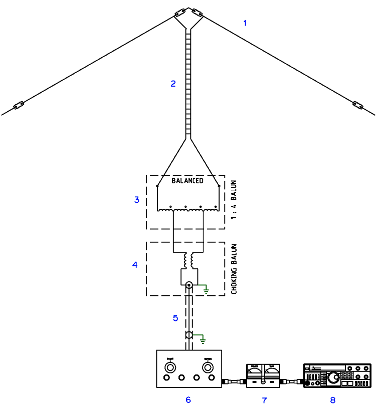
Figure
1 Multi-band Doublet, feed-lines and balun configuration
Basic Multi-band
Doublet Arrangement
(1)
Inverted 'V' Dipole. (42Mtr total length)
(2)
450 Ohm Ladder Line. (7.5Mtr)
(3)
1:4 Current Balun. See Balun Guanella Current 1:4 Single core
(4)
1:1 Choking Balun. See Balun Choke HF
(5)
LDF4-50 Heliax (3.5Mtr)
(6)
T-Match Tuner. See T Match Tuner
(7)
VSWR Meter.
(8)
HF Transceiver.
Construction
The
1:1 choking balun is a length of RG58 50ohm coax wound with 14 turns
on a single
FT240-43
ferrite toroid core. See
Fig 2 for the connection details and Balun
Choke HF for the 1:1
choking balun
details.
The
1:4 current balun has two ideally 100ohm transmission lines wound
evenly spaced in the same direction around a single FT240-43
ferrite toroid core. See
Fig 2 for the connection details and Balun
Guanella Current 1:4 Single core for balun details.
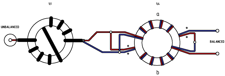
Figure
2 Detail Balun configuration

Photo
1 Balun housing for coax to ladder line interface.

Photo
2 Balun assembly.
Testing
The AIM 4170C antenna analyser recorded the balun impedance
transformation efficiency and common mode choking for a frequency
range from less than 100kHz to 30MHz.

Figure
3 AIM
4170C antenna analyser plot viewing a 200ohm resistive load through
the feed-line balun. Note the 200ohm resistor appears as 50ohms due to
the 1:4 balun ratio resulting in an ideal SWR of 1:1. This plot
shows an SWR of no greater than 1.7:1 with from 100kHz to 30MHz.

Figure
4 AIM
4170C antenna analyser plot viewing a 200ohm resistive load through
the feed-line balun. Note the 200ohm resistor appears as 50ohms due to
the 1:4 balun ratio. This plot shows 50 ~ 60 ohms from 100kHz to
30MHz.

Figure
5 The evaluation of the choking impedance of the balun over a bandwidth
from 0.5MHz- 30MHz.

Figure
6 Choking impedance to dB of choking. 20dB attenuation should be considered the minimum.
TOP
OF PAGE
Page
last revised 25
September, 2019
|