|
1:9 VOLTAGE BALUN -
VERSION 2
1:9 voltage balun using a FT140-43 Ferrite Toroid Core for 0.5MHz to 60MHz. Completed January 2022.
The 1:9 balun can be used to connect a balanced or unbalanced feed line to a balanced or unbalanced antenna, but it cannot be used for an unbalanced-to-unbalanced connection. Its purpose is to provide an impedance step-up, typically from 50 ohms to 450 ohms or from 75 ohms to 675 ohms. The 1:9 Voltage balun is designed around an FT140-43 Ferrite Toroid Core, and it is recommended to include a choking balun for an unbalanced feed line connection.
Similar to the version 1 balun, this version achieves greater transformation consistency over a wider bandwidth due to the evenly spaced winding. Refer to Photo 1 for visual reference.
Construction:
The 1:9 voltage balun is constructed with 5 turns wound evenly spaced around the FT140-43 Ferrite Toroid Core. The attention given to the even spacing of the winding significantly improves the efficiency and bandwidth of this balun compared to the version 1 balun.
To protect the enamelled copper wire from insulation puncture and to prevent the windings from slipping and maintain the desired winding spacing, the toroidal core is wrapped in overlapping layers of PVC electrical tape.
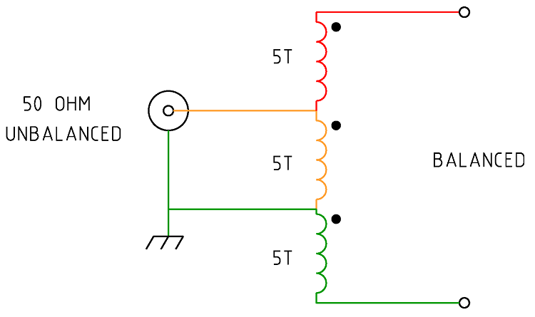
Figure 1 Schematic of the 1:9 Voltage balun

Figure
2 Wiring of the 1:9 Voltage balun.
Note this drawing shows
winding connections and not the number of turns required. See article
for details.
|
Type
|
Voltage
Balun
|
|
Ratio
|
1:9
|
|
Frequency
Range
|
0.5
~ 60MHz
|
|
Core
Used
|
FT140-43 Ferrite Toroid Core
|
|
Number
of turns
|
5
x 3 Evenly spaced.
|
|
Wire
size
|
1.25mm
Enamelled copper wire.
|
|
SWR
|
Low
1:1.06 (5.1MHz) High
1:1.27 (60.0MHz)
|
|
PEP
Power Handling.
|
Approximately
100W
|
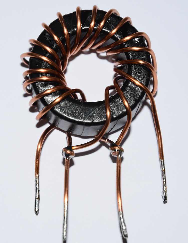
Photo 1 1:9 Voltage balun assembled.
The efficiency of the balun was evaluated across the desired bandwidth of 1.0 - 60MHz by testing the impedance observed from the unbalanced side to a resistive load applied on the balanced side using an antenna
analyser. The plot from the antenna analyser below depicts a 450ohm resistive load connected to the high side of the balun, with measurements taken at a nominal impedance of 50ohms. This
set-up is intended to present an approximate 50ohm load to the analyser
and ideally result in a 1:1 SWR.
The performance of the balun from 0.5MHz to 60MHz is generally good, exhibiting minimal reactance. However, above 30MHz, there is a gradual increase in reactance accompanied by a gradual rise in the
SWR. Despite this rise in reactance and SWR, the balun is still expected to perform well within the 50MHz amateur band.

Figure
3 SWR.
The AIM
4170C antenna analyser data
graphed a 450ohm resistive load through the voltage
balun from 0.5MHz to 60MHz. Note the 450ohm resistor appears as
50ohms due to the 1:9 balun ratio resulting in an ideal SWR of 1:1. The
SWR is shown to be consistently low for all Amateur radio bands with
a high of just overt 1:1.2 for the 6m band.
 Figure
4
The AIM 4170C antenna analyser data graphed a 450ohm resistive load through the voltage balun from 0.5MHz to 60MHz. Note the 450ohm resistor should ideally appears as 50ohms due to the 1:9 balun ratio.

Figure
5 The
AIM
4170C antenna analyser data
graphed a 450ohm resistive load through the voltage
balun from 0.5MHz to 60MHz. Note the 450ohm resistor should ideally
appears as 50ohms due to the 1:9 balun ratio. The impedance should
ideally be R (Resistance) at 50 ohms and X (Reactance) near zero
ohms. The Purple line shows the resistance component in ohms of the
Impedance and the Orange line shows the reactive component in ohms
of the Impedance, the + values for the reactance represent Inductive
reactance and the negative values represent the Capacitive
reactance.
Conclusion
The
Version 2 1:9 voltage balun using
a FT140-43
Ferrite Toroid Core represents a very efficient balun for a
frequency range from 0.5MHz to 60MHz at a power level of 100W PEP.
Power
Handling
For
Summary of suitable ferrite cores and core types for a frequency range
of 100 kHz to 50 MHz for power levels of 50W, 100W, and 500W
continuous and SSB. It assumes good thermal management and proper
balun design. See: Power
- Ferrite Core Design
Also
see other baluns and ununs:
BALUN
1:1 CHOKE & 1:4 BALUN HF
ladder feed-line to coaxial cable combination choke and 1:4 balun.
(0.1MHz - 30MHz).
BALUN 1:1
CHOKING Choking balun for
lower HF and MF bands. (200kHz - 10MHz).
CHOKING
1:1 BALUN - HF BANDS Reisert choking balun.
(1.0MHz - 30MHz). FT240-43 Ferrite Toroid Core.
CHOKING
1:1 BALUN - HF BANDS Reisert choking balun (1.5MHz - 30MHz). FT140-43
Ferrite Toroid Core.
CHOKING
1:1 BALUN - LOW VHF BAND Choking balun.
(10MHz - 60MHz). FT140-43 Ferrite Toroid Core.
BALUN
1:1 CURRENT 1:1 Guanella Current balun using a L15
ferrite core (1.8 - 30MHz).
BALUN
1:4 CURRENT 1:4 Guanella Current balun using a L15
ferrite core (1.8 - 30MHz).
BALUN
1:4 SINGLE CORE CURRENT 1:4 Guanella Current Balun, single FT240-43
ferrite toroid cores. (0.3MHz - 30MHz).
BALUN 1:1
VOLTAGE 1:1 Ruthroff voltage balun using a T-200-2 powdered iron
toroid core (1.8 - 30MHz).
BALUN 4:1
VOLTAGE 4:1 Ruthroff voltage balun using a T-200-2 powdered iron
toroid core (1.8 - 30MHz).
BALUN 6:1
VOLTAGE - VERSION 1 6:1 Voltage balun using a L15 ferrite toroid core (1.8 - 30MHz).
BALUN 6:1
VOLTAGE - VERSION 2 6:1 Voltage balun using a FT140-43 Ferrite
Toroid Core (1.8 - 30MHz)
BALUN 9:1
VOLTAGE - VERSION 1 9:1 Voltage balun using a L15 ferrite toroid core (1.8 - 30MHz).
BALUN 9:1
VOLTAGE - VERSION 2 9:1 Voltage balun using a FT140-43 Ferrite
Toroid Core (0.5 - 60MHz).
UNUN 9:1
VOLTAGE 9:1 voltage unun
using a T-200-2 powdered iron toroid core (1.8 - 30MHz).
UNUN 9:1
VOLTAGE VERSION 2 9:1 voltage unun using a L15 ferrite core (1.8
- 30MHz).
UNUN 9:1
VOLTAGE VERSION 3 9:1 voltage unun using a FT140-43 ferrite core
(0.5 - 60MHz).
TOP
OF PAGE
Page
last revised 27 January, 2026
|