|
The
Mk3 All Band HF Doublet is the same as the Mk2 version with the inclusion of a balun at
the interface from the coax to the open wire feed-line. This
antenna is normally used with a T-Match Antenna Tuning Unit.
November 2019
The All Band HF Doublet Mk3 is a 42-meter-long Inverted 'V' antenna, with an apex of 11 meters above the ground. It is designed to be a versatile antenna for all bands ranging from 160m to 10m.
Description:
The All Band HF Doublet is often referred to as a random length dipole because its length is generally determined by the available space, within reasonable limits. However, there are a couple of limitations regarding the ideal dipole length. Firstly, the antenna's efficiency begins to decline significantly if the dipole length is much less than half a wavelength for the lowest frequency band it is intended to operate on. Secondly, it is advisable to avoid lengths that result in extremely high impedance for the Matching Unit, as it may struggle to match such impedance. The second limitation can be easily addressed by adding or subtracting some length from either the dipole or the feed line. Often, just a meter of adjustment can rectify the issue. Although the antenna is shorter than half a wavelength at 1.8 MHz, being slightly over a quarter wavelength, it still provides usable access to this band.
The completed antenna system consists of a 42-meter centre-fed doublet, with each leg measuring 21 meters. It is suspended at the center and supported by a short 1-meter cross arm attached to the top of an 11-meter tower. The doublet is fed with 8 meters of 450-ohm ladder line, which is then connected to a 3.5-meter section of LDF4-50 heliax. This heliax section incorporates a combination choking balun and step-up balun (explained in detail below) and runs into the shack to a T-Match antenna matching unit.
The ARRL Handbook presents the results of a comparative study conducted on the All Band HF Doublet, both in a flat-top doublet and an inverted 'V' configuration. The conclusion drawn from the study is that both configurations offer a practical and flexible antenna, with the flat-top configuration providing a superior low-angle radiation pattern due to its greater overall height above the ground.

Photo
1 Multi-band Doublet and feed-lines. Other antennas are
the 2m band ground plane and 6m Ringo antenna November 2019
One of the disadvantages of this antenna system is its balanced nature, where each half of the doublet and feed-line configuration needs to mirror the other. Failure to achieve this balance will result in the feed-line receiving and radiating energy, leading to a distortion of the radiation pattern. Additionally, it can allow the feed-line to pick up stray signals from computers and other sources as it enters the radio room. However, despite this drawback, I have found that this antenna system is reasonably forgiving.
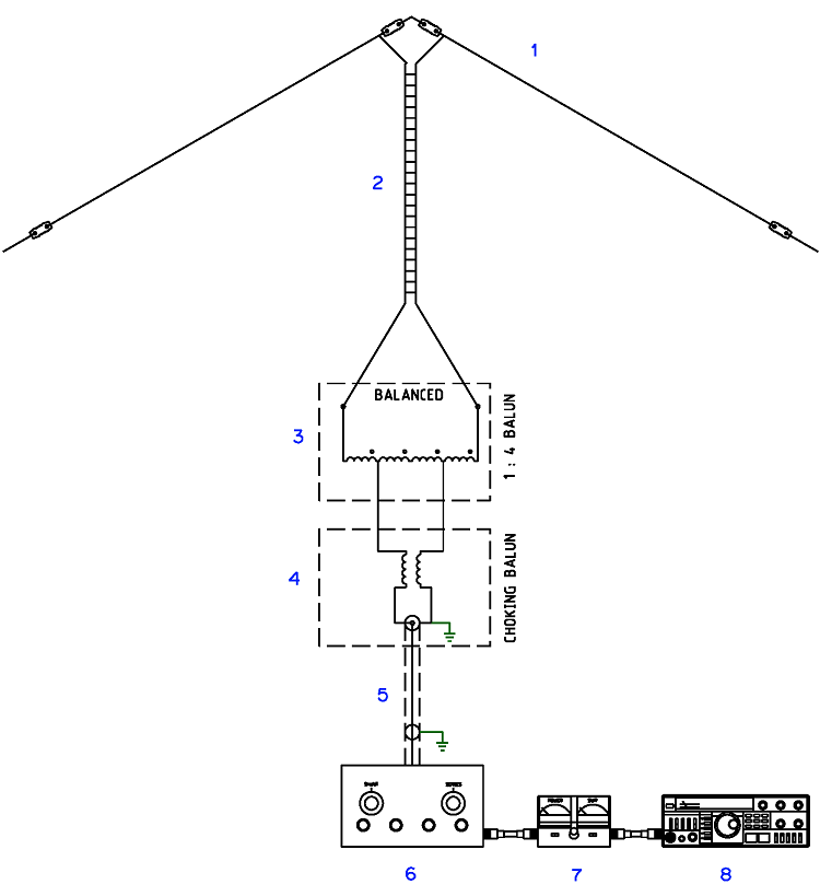
The unbalanced coaxial cable is connected to the balanced feed line using a combination of a 1:1 choking balun and a 1:4 impedance step-up balun in series. The setup of the antenna, feed lines, balun, and antenna is depicted in Figure 1 below.
The purpose of the 1:1 choking balun is to mitigate common mode RF currents on the coax cable, reduce noise pickup from within the building, and produce a balanced antenna system with a more predictable radiation pattern.
The inclusion of the 1:4 impedance step-up balun is to achieve a broader impedance matching range between the antenna/feed line and the nominal 50-ohm impedance of the coax.
Figure
1 Multi-band Doublet, feed-lines and balun configuration
Basic Multi-band
Doublet Arrangement
(1)
Inverted 'V' Dipole. (42Mtr total length)
(2)
450 Ohm Ladder Line. (7.5Mtr)
(3)
1:4 Current Balun. See Balun Guanella Current 1:4 Single core
(4)
1:1 Choking Balun. See Balun Choke HF
For details of the feed-lines and balun configuration. See HF feedline Choke & Balun
(5)
LDF4-50 Heliax
(3.5Mtr)
(6)
T-Match Tuner. See T Match Tuner
(7)
VSWR Meter.
(8)
HF Transceiver.
Construction
The 1:1 choking balun is created by winding a length of RG58 50ohm coax around a single FT240-43 ferrite toroid core, forming 14 turns. Detailed connection information and specifics about the
Balun Choke HF
for the 1:1 choking balun can be found in Figure 2.
For the 1:4 current balun, two ideally 100ohm transmission lines are wound evenly spaced in the same direction around a single FT240-43 ferrite toroid core. The connection details and information about the
Balun Guanella Current 1:4 Single core
can also be found in Figure 2.
The inverted 'V' doublet was constructed using 42m of standard 4mm2, 7 strand copper wire. Glazed porcelain electric fence insulators were used at the ends and 'V' apex attachments. The apex of the 'V' is attached to a small steel cross-arm located at the top of the 11m tower. The doublet is fed with 8m of 450ohm ladder line, which drops vertically away from the 'V' apex and connects to an
aluminium enclosure housing the baluns.
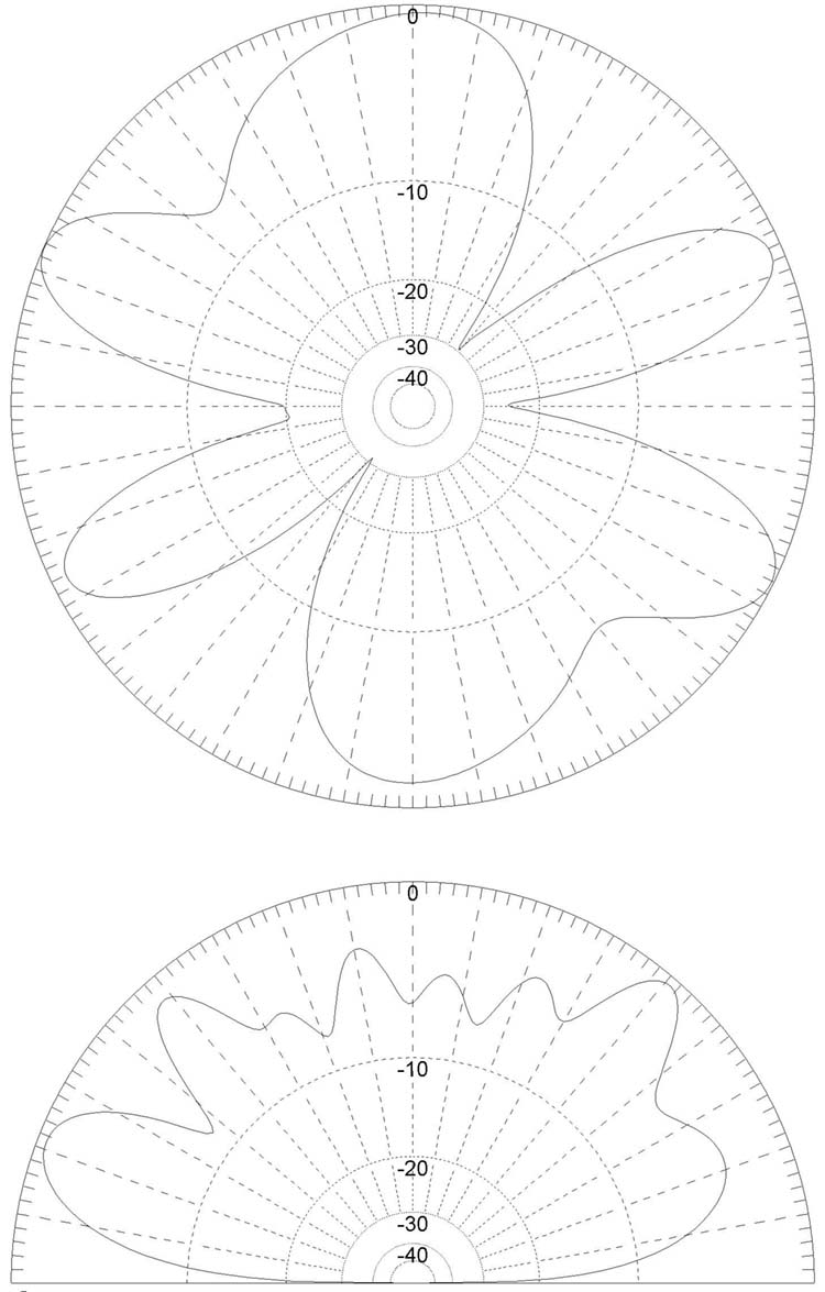
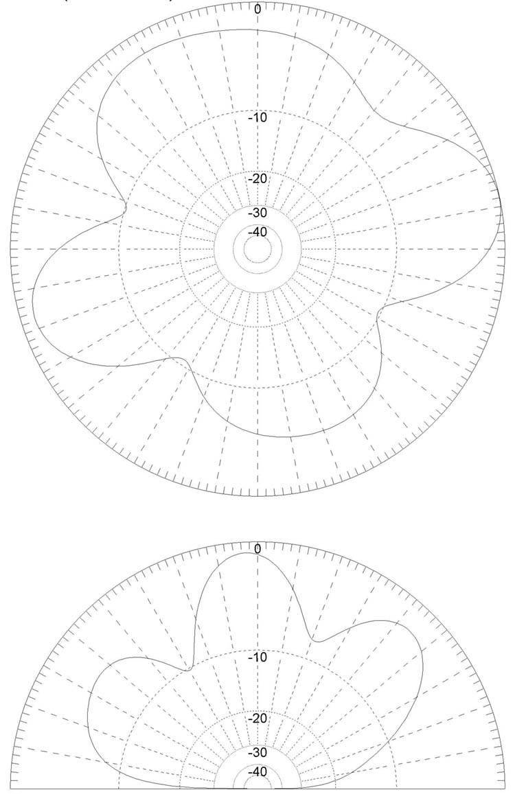
MMANA-GAL
antenna analyser
modelled radiation plot for 30,
20, 17, 15, 12 and 10m bands.
 |

|
|
Figure 6 Modelled radiation plot for the 10m band
|
Figure
7 Modelled radiation plot for the 12m band
|
|

|

|
|
Figure 8
Modelled radiation plot for the 15m band
|
Figure 9
Modelled radiation plot for the 17m band
|

|
|
|
Figure 10
Modelled radiation plot for the 20m band |
Figure 11
Modelled radiation plot for the 30m band |
Summary
The random length all
band doublet represents some clear advantages in cost and
operational flexibility within the limitations of the average
Australian suburban block. There for if you can have only one HF
antenna the random length all band doublet would be a pretty good
choice.
References
WIRE
SPLICE - INLINE
Wire splicing for inline joining of aerial
wire.
WIRE
SPLICE TERMINATION
Wire splicing for terminating an antenna
aerial wire or guy wire to a strain insulator or thimble.
WIRE
SPLICE TERMINATION & TAIL
Wire splicing for terminating an antenna
aerial wire to a strain insulator with a tail for connecting to the
feed line.
The
ARRL Antenna Book.
The
1990 ARRL Hand Book.
The
above radiation plots were produced using MMANA-GAL Antenna Analyser
software by JE3HHT, Makoto (Mako) Mori at http://hamsoft.ca/
|

