|
MARCONI 'T' ANTENNA CONFIGURATION
Adapting the
main
HF Doublet Antenna as a type of ‘T’ Antenna was achieved by bonding the ladder line in the shack
and connecting directly to the T-Match antenna tuner.
HOME > PROJECT
> ALTERNATE
CONFIGURATIONS >
Principal
of the 'T' Antenna
The
Marconi ‘T’ Antenna is essentially a shortened vertically
polarized monopole antenna that is used for lower frequency bands,
typically below 4 MHz and ideal for use on the 160m (1.8MHz) amateur
band.
Vertical
antennas are ideally suited to long distance broadcast type
communication due to the low angle of radiation and Omni-directional
characteristic.
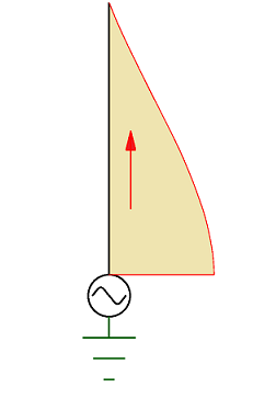
At low frequencies a full quarter
wavelength
(λ/4) monopole antenna as shown in Fig 1 may be impractically
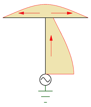
large, therefor a simple solution is a ‘T’
Antenna. The ‘T’ section of the antenna will produce RF currents
directed in opposite directions as shown in Fig 2, causing the
radiated energy to be cancelled out far from the antenna. The two
‘T’ arms act as a capacitance hat increasing RF current in the
upper portion of the shorter vertical section, increasing the
radiation resistance that will allow the antenna to be more easily
matched to the feed line and improve the efficiency of the system.
|
|
|
| Fig
1
RF current
distribution on a λ/4 monopole antenna |
Fig
2 RF
current distribution on a short monopole
T antenna |
The
All Band Doublet configured as a 'T' Antenna
The main HF antenna is an All Band Doublet fed with ladder line and
matched with a T-Match antenna tuner including a 1:4 current balun
that gives access to all HF bands including the 160m band. With a view to
get better performance particularly on lower frequency bands this
antenna was reconfigured as a type of Marconi ‘T’ Antenna by
simple bonding the ladder line in the shack and connecting directly
to the T-Match antenna tuner.
The ‘T’ Antenna
requires a counterpoise to work well and this will achieved
at least initially by using the galvanized steel building roof to serve
this purpose.
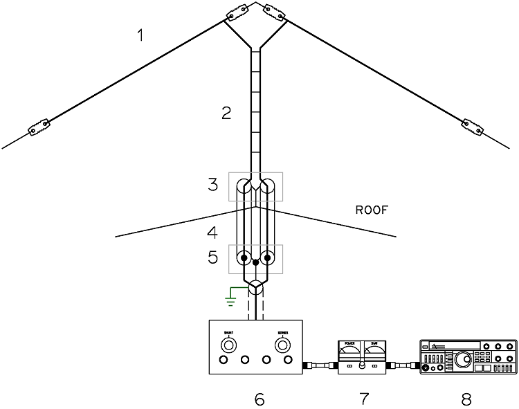
Fig
3 Multi-band
dipole antenna configured as a type of 'T"
Antenna
Basic
Multi-band
dipole antenna configured as a type of 'T"
Antenna
(1) Inverted 'V'
Dipole 42Mtr total length
(2) 450 Ohm Ladder
Line 7.5Mtr length.
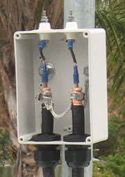
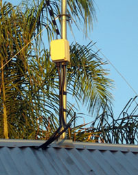
(3) Junction box
(Ladder line - twin heliax interface)
(4)
Twin heliax 3.5Mtr
length.
(5)
Twin SO259 bulkhead sockets
(6) T-Match Tuner.
See T-Match
Tuner
(7) VSWR Meter.
(8) HF Transceiver.
|
|
|

|
| Photo#1 Junction box (Ladder line - twin heliax interface) |
Photo#2 Junction box (Ladder line - twin heliax interface)
assembly |
Photo#3
Twin
SO259 bulkhead sockets and Ground connection. |
Antenna
Modelling with MMANA-GAL

Fig 4 All Band Doublet modelled with MMANA-GAL
in the normal configuration at 1.825MHz.

Fig 5 All Band Doublet re-configured to a 'T' Antenna and modelled with MMANA-GAL
at 1.825MHz.
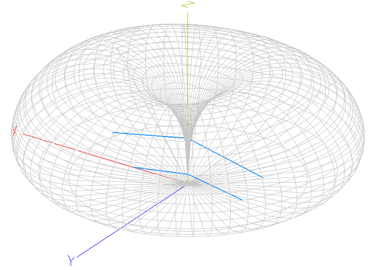
Fig 6 'T' Antenna 3D radiation pattern modelled with
MMANA-GAL
at 1.825MHz.
WSPR
Measurements
Comparison of the Multi-band
dipole antenna with the same antenna configured as a 'T"
Antenna used
for operations on the 160m amateur band.

WSPR data has been graphed using
Excel. Horizontal axis = UTC Time, Vertical axis = dB below the
noise floor.
Antenna#1: Multi-band
dipole with T-Match tuner and 4-1
Current Balun
Antenna#2: 'T"
Antenna configuration with T-Match tuner
VK6YSF WSPR Signal received
by:VK2KRR
Distance: 2832km
Grid location: QF34mr
dBm: 37
TOP
OF PAGE
Page
last revised 27 January, 2026
|