|
QUARTER-WAVE IMPEDANCE TRANSFORMER Classic
quarter-wave impedance transformer for matching Yagi antenna folded
dipole driven element.
Published in the WANSAC (Western
& Northern Suburbs Amateur Radio Club) monthly club magazine.
Issue
June 2026
http://www.wansarc.org.au/
Classic
quarter-wave impedance transformer
By
Peter Miles – VK6YSF
Pursuing
my goal of developing a practical and repeatable method for
designing and constructing Yagi antennas across various bands and
gain levels, the challenge of matching feed-lines to the driven
element naturally arose. This led me to revisit one of my preferred
matching techniques: the classic quarter-wave impedance transformer
used with a folded dipole driven element - a technique widely used
by commercial antenna manufacturers for good reasons.
A
typical folded dipole has dimensions where A = λ/2 and B =
λ/4 − D (a small gap for the feed connection). All
dimensions are typically multiplied by approximately 0.95 to allow
for end effects and conductor diameter. Dimension C represents the
spacing between conductors; while it should be relatively small, it
is usually determined by practical construction considerations.
For
a typical two-wire folded dipole (with equal-diameter conductors),
the feed-point impedance at resonance is approximately 300 Ω.

Where:
However,
in real-world builds, the final impedance is affected by conductor
spacing, element diameter, nearby parasitic elements, and mounting
hardware. These factors reduce the feed-point impedance in practice
to values between 180 - 240 Ω for the folded dipole driven
elements in Yagi antennas.
A
quarter-wave impedance transformer is an elegant RF technique where
a section of transmission line performs impedance matching without
requiring discrete components such as coils or capacitors.
This
works because a transmission line not only carries energy but also
transforms impedance along its length. When the line is exactly one
electrical quarter wavelength long at the operating frequency, it
transforms the load impedance to a different value at its input.
By
selecting the transmission line with the correct characteristic
impedance, the transformed impedance can match the source, allowing
efficient power transfer.
This
technique is inherently frequency-dependent. If the frequency
changes significantly, or the physical length is not precise, the
impedance transformation will no longer be exact. As a result,
quarter-wave coax transformers are simple and low-loss, but not
suitable for broadband applications.
A
homebrew folded dipole with a 75 Ω coaxial transformer section
routed through the folded dipole creates a robust, weather proof and
professional looking design. The transformer section is connected at
the dipole feed-point, and the other end provides a convenient
connection, via an N connector or similar, to the 50 Ω coaxial
feedline.

Photo
1.
Completed homebrew
Folded Dipole for 435MHz with heat-shrink x 2 over coax connection
and rubber grommet for the coax exit.

Photo
2.
The coax impedance
transformer section terminated to spade lugs pop riveting to the Folded Dipole
tube.
Fig 1.
Quarter-wave
impedance transformer configuration.
Zin
= impedance seen looking into the matching section (from
the 50Ω coax feed-line).
Zo
= required characteristic impedance of the matching section.
ZL
= load impedance (200Ω antenna impedance).

What
this means is that a λ/4
section of 100Ω transmission line connected to the feed point
of a folded dipole with a nominal impedance of around 200Ω
will present a near 50Ω impedance at the end of the normal
coax cable to the radio with a 1:1 SWR.
While
100 Ω coax is ideal in this case, it is not commonly available.
However, 75 Ω coax (such as RG6) is widely available and
provides a practical compromise. Even commercial antenna
manufacturers often use 75 Ω sections to match folded dipoles.
Reorganizing
the formula to make Zin the subject allows evaluation of 75Ω
(RG6) coax as a quarter-wave
impedance transformer.
The
75Ω coax is a compromise
and while not a perfect transformer it will result in an SWR of
approximately 1.8:1 which is quite acceptable for
most systems and commercially
acceptable. The spacing between the driven element and the reflector
and even the first director can be adjusted to increase or decrease
the loading on the driven element and dramatically improve this
match while not compromise the overall gain of the antenna.
Fig
2.
Y axis (Vertical) shows Zo and the ideal impedance
of the matching section in Ohms and X axis
(Horizontal) shows ZL and the antenna load impedance
in Ohms to achieve 1:1 SWR.
In
practice, the physical length of the matching section must account
for the cable’s velocity factor (VF).
For RG6, VF ≈ 0.80.
Example
of a matching
section for 1270 MHz
If
a single quarter-wave section is not physically convenient, odd
multiples (λ/4, 3λ/4, 5λ/4, etc.) can be used.
However, longer sections introduce additional loss, so the shortest
practical length should be used.
Interestingly
it is sometimes suggested that a full wavelength of RG6 coax can be
used as a matching section. In this example, a full wavelength at
1270 MHz is approximately 236mm.
Notably,
this is very close to 5 × (λ/4), which equals 235mm when
velocity factor is applied. This agreement is coincidental for RG6
with a VF of 0.80 and should not be taken as a general rule -
matching behaviour is determined by quarter-wave transformations,
not full-wave sections.
Testing
Measure
electrical length (phase method)
First,
a standard S11 calibration is performed on the NanoVNA at the end of
the test lead/cable.
A
length of RG-6 coax is then connected to the NanoVNA, with the far
end left either open or shorted. One method should be chosen and
used consistently. In this case, an open circuit was used.
The
NanoVNA is set to display S11 phase, and a marker is placed at the
target frequency of 1270 MHz.
The
phase reading at this frequency is noted as the starting reference.
The
coax is then trimmed incrementally, typically one to two millimetres
at a time. After each cut, the cable is reconnected and the phase at
the marker frequency is observed.
As
the cable is shortened, the phase changes progressively. Trimming
continues while monitoring this phase shift.
When
the phase has changed by approximately 180 degrees from the initial
reference, the cable is at an electrical quarter wavelength, or an
odd multiple of a quarter wavelength.
If
the far end is open, the phase will be close to ±180 degrees at
this point. If the far end is shorted, the phase will be close to 0
degrees.
·
Open
circuit → phase ≈ ±180°
·
Short circuit →
phase ≈ 0°
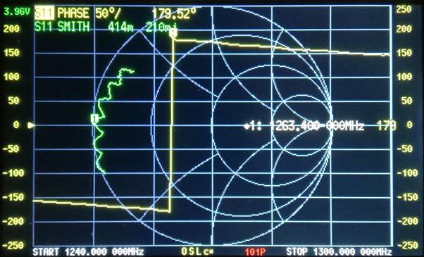
Photo
2.
The NanoVNA S11 phase display
(yellow trace) shows that at 1263.4 MHz the phase reaches +180°
(+179.52°). At slightly lower frequencies, the display transitions
to -180°, appearing as a vertical shift. This indicates that the
RG-6 coax is at an electrical quarter wavelength or an odd multiple
at this transitions point.
In
this instance, the length corresponds to 5λ/4 (about 265mm
including connectors and termination lugs).
The
display spans the 23 cm band from 1240 MHz to 1300 MHz. Across this
range, the phase varies smoothly between approximately -150° and
+150°, indicating that the coaxial transformer remains relatively
effective across the full band with maximum efficiency at 1263.4
MHz.
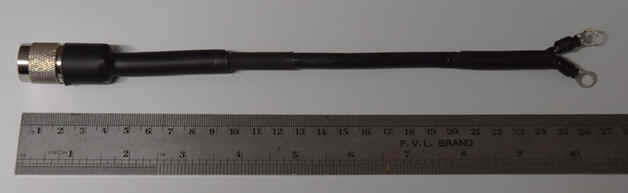
Photo
3.
The 5λ/4 impedance
transformer section (about 265mm including
connectors and termination lugs).
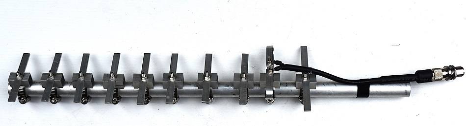
Photo
4.
The 5λ/4 impedance
transformer section connected to a new 23cm band Yagi antenna.
Modified
Coax Cable
There
are situations where the use of a standard, readily available
coaxial cable such as 75 Ω RG-6 is not sufficiently suitable
for use as a quarter-wave transformer. This can occur, for example,
when the feed-point impedance of a folded dipole is greater than 200
Ω, as is often the case with a stand-alone folded dipole.
As
100 Ω coaxial cable, or cable with a similar impedance, are
difficult to obtain, an alternative approach is to modify a section
of standard coax.
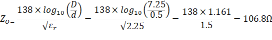
One
method is to alter the geometry of the cable. For example, replacing
the centre conductor of standard RG-213 coax with 0.5 mm diameter
copper wire increases the ratio between the outer and inner
conductors. This modification results in a section of coax with an
approximate characteristic impedance of 107Ω. RG-213 was chosen
as it is easier to remove the centre core in this coax.
RG-213
Coaxial Cable Specifications
Characteristic
Impedance: 50 Ω
Nominal
Impedance Tolerance:
±2–3 Ω
Capacitance:
~100 pF/m
Velocity
Factor: ~0.66
Dielectric:
Solid polyethylene (εr ≈ 2.25)
Centre
conductor diameter ≈ 2.25 mm
(nominal)
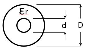
εr
(Dielectric: solid polyethylene) = 2.25
D
(dielectric OD) Outer conductor inner diameter = 7.25 mm
d (New centre conductor) =
0.5 mm
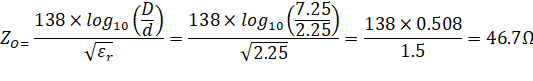
The
below calculation done for un-modified RG-213 Coaxial Cable
specifications and interestingly not quite
50Ω
– possible due to rounding errors.
Conclusion
The
coaxial quarter-wave transformer is a practical, low-loss, and
effective method for matching feed-lines to folded dipole driven
elements in mono-band Yagi antennas.
References:
6
Element Yagi-Uda antenna for the 70cm Band (430MHz to 440MHz)
https://vk6ysf.com/yagi_435mhz_6el_20230201.htm
10
Element Yagi-Uda antenna for the 23cm Band (1250MHz to 1300MHz) https://vk6ysf.com/yagi_1290mhz_10el_20260327.htm
ARRL
Handbook for Radio Communications
American Radio Relay League.
VHF
UHF Manual 4th Edition by G. R. Jessop, G6JP
RSGB.
TOP
OF PAGE
Page initiated
03
February, 2026
Page
last revised 03 February, 2026
|