Peter Miles
Northam, Western Australia QRZ Page: VK6YSF
Email
Social
Media
Buy me a coffee
If you found information on this site interesting, beneficial, or learned something new, please consider buying me a cup of coffee by clicking the coffee cup below.
It helps keep the website going and is greatly appreciated.
435MHz
(70cm BAND) 6 ELEMENT YAGI-UDA ANTENNA
6
Element Yagi-Uda
antenna for the 70cm Band (430MHz to 440MHz) . February 2023
The primary objective was to explore a
practical and straightforward construction technique for VHF and UHF
Yagi antennas, ensuring satisfactory performance. Additionally,
there was a particular interest in building a compact 6-element Yagi
antenna for local operations, while keeping the option open to
incorporate additional elements for potential future performance
enhancements.
To achieve these goals, a key focus was placed on developing an
element mounting technique that facilitated easy installation and
replacement of the elements. It was also essential to enable
effortless adjustment of the element attachment point on the boom
without the need to drill holes into the boom itself. Moreover,
careful consideration was given to designing the antenna in a manner
that would facilitate its recycling into another antenna when it is
no longer required.
Photo 1 Complete435MHz
6 element Yagi.
Antenna
details
Frequency:435 MHz, (useful from 431 to 442)
Wavelength:690 mm
Rod
Diameter:10 mm
Boom
Diameter:20 mm
Boom
Length:682 mm
(Plus additional length for mounting).
Elements:6
Gain:9 dBd
(approximately).
Ref
Element
Length
(mm)
Position
fromReflector (mm)
Note
R
Reflector
343
0
D
Driven
See details
145
Distance Reflector - Dipole: 145 mm
D1
Director 1
317
276
D2
Director 2
314
414
D3
Director 3
312
552
D4
Director 4
309
690
Table 1 Yagi dimension
details.
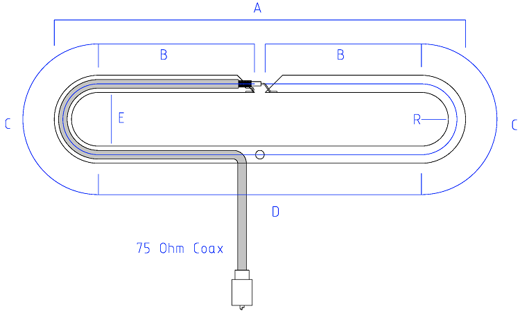
Folded Dipole
The dimensions of the folded dipole for 435MHz are detailed in Table 2,
denoted in millimetres. The fold spacing, set at 77mm, was
determined based on the bending tool used for the internal part of
the element material. In this instance, a 12mm Aluminium tube was
chosen to align with the tube bending tool. It should be noted that
modifying the tube diameter will have repercussions on other
dimensions specified in the table.
Because the fold spacing is relatively large in comparison to the
wavelength, the folded dipole exhibits characteristics that resemble
a loop antenna. The length of the loop is closer to a full
wavelength, while the overall end-to-end length is significantly
shorter than the conventional half wavelength commonly associated
with a dipole antenna. Photo 1 presents a comprehensive view of the
complete 435MHz Yagi, showcasing the relatively compact size of the
folded dipole in comparison to the other elements.
To achieve the desired impedance matching, a 75ohm coaxial cable is
employed as a Series Section Transformer in series with a 50ohm feed
line connected to the radio. The length of the Series Section
Transformer is determined to be 685mm, with a detailed explanation
of the reasoning behind this specific length provided in subsequent
text.
Frequency
(MHz)
A
B
C
D
E
R
Total
element length
(Centre line)
Inner
Centre
Inner
Inner
435
280
80
138
147
180
77
38
634
Table 2 Folded
dipole dimension details. All dimensions are in mm.
Photo 2 Folded
Dipole showing the installation of the RG59 75ohm coax. Semi-rigid PVC
agricultural tube and two heat-shrink tubes readied to seal the
connection.
Photo 3 RG59
75ohm coax terminated to spade lugs with the spade lugs drilled with 3mm
holes for pop riveting to the tube.
Photo 4 RG59
75ohm coax terminated to spade lugs pop riveting to the tube.
Photo 5 Completed
Folded Dipole with heat-shrink x 2 over coax connection and rubber grommet for
RG59 75ohm coax entry.
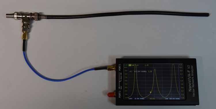
The
Series Section Transformer length is determined in the below NanoVNA
set up.
The Series Section Transformer coax is employed as a segment of coaxial cable with a characteristic impedance that differs from the main coaxial feed. In this case, the main coax line has a characteristic impedance of 50ohms, while the Series Section Transformer utilizes a 75ohm RG59 coaxial cable.
Determining the appropriate length of the Series Section Transformer involves initial calibration of the NanoVNA to the end of the 'Blue' coax in the provided
set-up. A BNC 'T' connector is then connected, with a 50ohm load attached to one side of the 'T' connector, and the RG59 coaxial cable section being tested connected to the other side. The objective is to achieve a practical length that results in a low standing wave ratio
(SWR) centred around 435MHz.
The practical approach entails selecting a length that exceeds a full wavelength for 435MHz and progressively trimming it down until the SWR dip aligns with the frequency of 435MHz. The determined length for the Series Section Transformer utilizing the RG59 coaxial cable under test was found to be 685mm.
Photo 6 NanoVNA
set up for determining the Series Section Transformer length.
If
the Series Transformer Section
is not required to run through the folded dipole tube and will work
the same if connect and lead away along the boom.
This arrangement was test revealing the same SWR result.
A
4:1 coax balun was also connected and produced similar SWR results
as the Series Transformer Section method.
Construction
The element mounting assembly shown in Figure 1 and Photo 7 consists of a stainless steel hose clamp with a 5mm stud hole drilled in the strap. A countersunk-headed set screw is then mounted with the flat head against the boom, as depicted in Photo 7. The hose clamp stud mount eliminates the need for drilling any holes into the boom and allows for infinite lateral adjustment along the boom.
The element mounting bracket, as seen in Photo 7, 8, and 9, is made of 12 x 12mm aluminium channel. This aluminium channel features a 'V'-cut notch that facilitates the attachment of elements of various diameters. Additionally, a lower notch is cut out to ensure the bracket mounts flat against the boom and remains clear of the hose clamp strap. It is crucial to accurately cut the 'V' notch to achieve symmetrical element mounting.
Figure 1
Element
to Boom mounting arrangement.
Figure
2Element
to Boom mounting bracket.
Photo 7 Element to Boom mounting
assembly.
Photo 8 Element to Boom mounting
assembly.
Photo 9 Folded
dipole using identical Boom mounting
assembly.
Modelling
Figure
3Modelling
with MMANA antenna modelling application.
Testing
Once the antenna is full
assembles the SWR was measured with a short length of 50ohm coax
connected to the antenna's Series
Transformer Section coax with final adjustment made by moving the
antenna's reflector element for the best SWR value.
Photo 9 NanoVNA
SWR sweep from 425MHz to 445MHz.
Chart 1
Gives a
clearer view of the 435MHz Yagi antenna's SWR from 430MHz to 444MHz with
a useful
range from 431MHz to 442MHz
Antenna Gain Range Testing
This is the most important antenna measurement because even if all other measurements such as SWR and resonance are satisfactory, if the antenna fails to achieve at least an approximation of the desired or predicted gain, it can be considered a failure. Measuring antenna gain is perhaps one of the most challenging tasks to accomplish successfully, as it requires a large and unobstructed area, especially free from metallic obstacles that can significantly distort the antenna's ideal radiation pattern. Figure 4 below illustrates an example of an antenna gain range test using the popular
NanoVNA.
Figure
4 Shows
the basic antenna gain range test set-up.
Source
Antenna is the 435MHz Source dipole antenna.
Reference
Antenna is the 435MHz Reference dipole antenna. A measurement will be
taken with this antenna to determine the base line. This antenna is
replaced with the Yagi antenna and the return loss measured that
will show the gain in dB with respect to the Reference dipole
antenna.
NanoVNA
set to LOGMAG with a display of typically -2 ~ +18dB and calibrated
to remove the lead characteristics from the measurements and with
the reference antenna and set the base line to 0 as per Fig 4.
Photo 10 NanoVNA
showing the Fig 4 set-up and calibrated for the base line to be
zero.
Figure
5 Shows
the basic antenna gain range test set-up with the antenna under test
in place.
d
Is the distance between the Source dipole antenna and the Reference
dipole antenna and while not critical needs to be between 2 and 3
wavelengths apart. In the set up the two antennas were placed
2mtr
(approximately 3 wavelengths) apart.
The ideal separation for antenna gain testing depends on various factors such as the frequency of operation, the type of antennas being tested, and the testing environment. Generally, a separation of at least 2-3 wavelengths is recommended between the transmitting and receiving antennas to minimize interference and achieve accurate measurements.
larger antenna separations can give false readings due to ground
reflection and other multi-path effects.
The
distance (d) between the source distance to the antenna under test ( 435MHz Yagi
antenna) is taken from the source dipole to the Yagi's driven
element.
The suitable height above ground for antenna gain testing depends on various factors, including the type of antenna, the desired testing accuracy, the operating frequency, and the testing environment. As a general guideline, a height of at least
1 to 2 wavelengths above ground is recommended to minimize ground effects and reflections.
The antennas in this
set-up are positioned 1.5 meters above the ground, which is slightly over 2 wavelengths at 435 MHz.
Measurements with horizontal polarization are less affected by ground bounce and can provide more accurate and consistent gain values. Horizontal polarization also helps simulate more ideal free-space conditions, which is important for accurate gain characterization.
Target
performance.
Ageneral guideline is that a well-designed and properly constructed 6-element Yagi antenna can typically provide a gain of around 8 to 10 dBd (decibels over dipole) or approximately 10 to 12 dBi (decibels over isotropic).
Test
Results.
The
test results recorded a 10 dB return gain (9.98) for the 6-element Yagi antenna compared to the 435MHz Reference dipole antenna. This gain is defined as 10 dBd for the 6-element
Yagi. Considering that a dipole antenna in free space has a gain of 2.15 dB over the theoretical isotropic antenna, the 6-element Yagi demonstrates an approximate gain of 12
dBi. This gain closely matches the ideal gain predicted for the 6-element Yagi antenna.
Photo 11 NanoVNA
showing the Fig 5 set-up and displaying Yagi antenna's gain compared
with the reference dipole antenna.
Repeaters Page Updated
- Expanded and refreshed information on VHF and UHF repeaters across Western Australia's Central Coast, Perth, the Avon Valley, and the Peel region. New AllStar Link information has also been added, including linked repeater details and
gateway information across the State.