|
1270MHz
(23cm BAND) 10 ELEMENT YAGI-UDA ANTENNA
10
Element Yagi-Uda
antenna for the 23cm Band (1250MHz to 1300MHz) . April 2026 Under
development
Exploring further practical and straightforward construction technique for VHF and UHF
Yagi antennas and ensuring satisfactory performance. Additionally,
there was a particular interest in building a compact 10-element Yagi
antenna for local operations, while keeping the option open to
incorporate additional elements for potential future performance
enhancements and modifications.
To achieve these goals, a key focus was placed on developing an
element mounting technique that facilitated easy installation and
replacement of the elements. It was also essential to enable
effortless adjustment of the element attachment point on the boom
without the need to drill holes into the boom itself. Moreover,
careful consideration was given to designing the antenna in a manner
that would facilitate its recycling into another antenna when it is
no longer required.
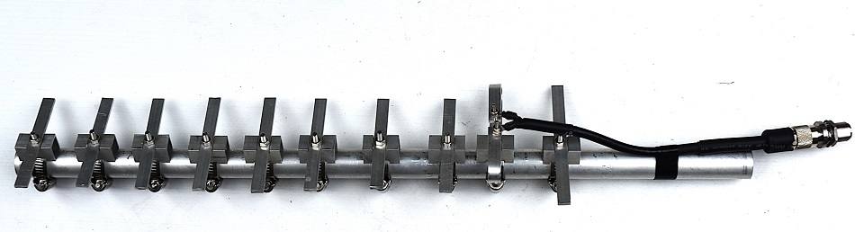
Photo 1
Complete 1270MHz
10 element Yagi antenna including a Series Section coaxial impedance transformer.
Antenna
details
Frequency:
1270 MHz, (useful from 1250 to 1300)
Wavelength:
233 mm
(23.3 cm)
Element
width:
10 mm
Boom
Diameter:
20 mm
Boom
Length:
430 mm
(Plus additional length for mounting).
Elements: 10
Gain: 11 dBd
(approximately).
|
Ref
|
Element
|
Element
Length
(mm)
|
Position
from Reflector (mm)
|
Note
|
|
RE
|
Reflector
|
111
|
0
|
|
|
D
|
Driven
|
See details
|
47
|
Distance Reflector - Dipole:
47 mm
|
|
D1
|
Director 1
|
96
|
93
|
|
|
D2
|
Director 2
|
96
|
140
|
|
|
D3
|
Director 3
|
96
|
186
|
|
|
D4
|
Director 4
|
96
|
233
|
|
|
D5
|
Director 5
|
96
|
279
|
|
|
D6
|
Director 6
|
96
|
326
|
|
|
D6
|
Director
7
|
96
|
372
|
|
|
D8
|
Director
8
|
96
|
419
|
|
Table 1 Yagi
antenna dimension
details.
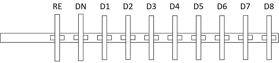
Fig
1 general Yagi antenna layout in
relation to Table 1.
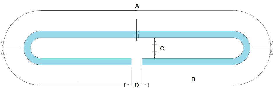
Folded Dipole
The dimensions of the folded dipole for 1270MHz are detailed in Table 2,
denoted in millimetres. The fold spacing, set at 20mm, was
determined based on the bending tool used for the internal part of
the element material.
Because the fold spacing is relatively large in comparison to the
wavelength, the folded dipole exhibits characteristics that resemble
a loop antenna. The length of the loop is closer to a full
wavelength, while the overall end-to-end length is significantly
shorter than the conventional half wavelength commonly associated
with a dipole antenna. Photo 1 presents a comprehensive view of the
complete 1270MHz Yagi, showcasing the relatively compact size of the
folded dipole in comparison to the other elements.
To achieve the desired impedance matching, a 75ohm coaxial cable is
employed as a Series Section Transformer in series with a 50ohm feed
line connected to the radio. The length of the Series Section
Transformer is determined to be 255mm, with a detailed explanation
of the reasoning behind this specific length provided in subsequent
text.
|
Frequency
(MHz)
|
A
|
B
|
C
|
D
|
Total
element length
(Centre line)
|
|
Inner
|
Centre
|
|
1270
|
105
|
48
|
40
|
147
|
10
|
200
|
Table 2 Folded
dipole dimension details. All dimensions are in mm.
The
Series Section coaxial quarter-wave impedance transformer
For
a typical two-wire folded dipole (with equal-diameter conductors),
the feed-point impedance at resonance is approximately 300Ω.

Where:
- N
= Number of conductors
- Z
dipole = Half-wave dipole impedance ≈ 73
Ω
However,
in real-world builds, the final impedance is affected by conductor
spacing, element diameter, nearby parasitic elements, and mounting
hardware, all of which tend to lower the impedance. Typically, 180 -
240 Ω is very common for Yagi driven elements.
A
quarter-wave impedance transformer is an elegant RF technique where
a section of transmission line performs impedance matching without
requiring discrete components such as coils or capacitors.
This
works because a transmission line not only carries energy but also
transforms impedance along its length. When the line is exactly one
quarter wavelength long at the operating frequency, it transforms
the load impedance to a different value at its input.
By
selecting the transmission line with the correct characteristic
impedance, the transformed impedance can match the source, allowing
efficient power transfer.
This
technique is inherently frequency-dependent. If the frequency
changes, or the physical length is not precise, the impedance
transformation will no longer be exact. As a result, quarter-wave
coax transformers are simple and low-loss, but not suitable for
broadband applications.
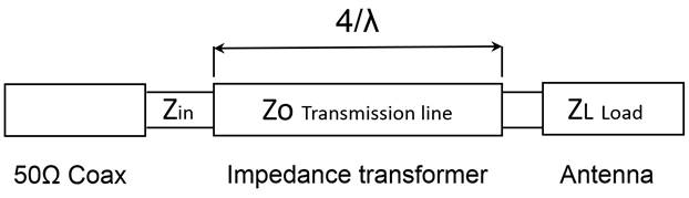
Fig
2.
Quarter-wave impedance transformer configuration.
Zin
= impedance seen looking into the matching section (50Ω
coax feedline).
Zo
= characteristic impedance of the matching section.
ZL
= load impedance (200Ω antenna impedance).

What this means is that a λ/4
section of 100Ω connected to the feed point of a folded dipole
with a nominal impedance of around 200Ω will present a near
50Ω impedance at the end of the normal coax cable to the radio
with a 1:1 SWR.
While
100 Ω coax is ideal in this case, it is not commonly available.
However, 75 Ω coax (such as RG6) is widely available and
provides a practical compromise. Even commercial antenna
manufacturers often use 75 Ω sections to match folded dipoles.
Reorganizing
the formula to make Zin the subject allows evaluation of 75Ω
(RG6) coax as a quarter-wave impedance transformer.
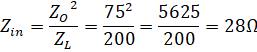
The
75Ω is a compromise and while not a perfect transformer it
will result in an SWR of approximately 1.8:1 which
is quite acceptable for most systems and commercially acceptable.
In practice, the physical length
of the matching section must account for the cable’s velocity
factor (VF).
For RG6, VF ≈ 0.80.
Example of a matching
section for 1270 MHz
- Free-space
λ (Wave Length for 1270
MHz) ≈ 236mm
- Quarter-wave
≈ 0.59mm
- With
VF = 0.8 will result in ~47mm coax matching section.
If a single quarter-wave section is not physically
convenient, odd multiples (λ/4, 3λ/4, 5λ/4, etc.) can
be used. However, longer sections introduce additional loss, so the
shortest practical length should be used.
Interestingly it is sometimes
suggested that a full wavelength of RG6 coax can be used as a
matching section. In this example, a full wavelength at 1270 MHz is
approximately 236mm.
Notably, this is very close to 5 × (λ/4),
which equals 236mm when velocity factor is applied. This agreement
is coincidental for RG6 with a VF 0.80 and should not be taken as a
general rule - matching behaviour is determined by quarter-wave
transformations, not full-wave sections.
Testing
Measure electrical
length coaxial quarter-wave
impedance transformer
(phase method)
First, a standard S11 calibration is
performed on the NanoVNA at the end of the test lead.
A length of RG-6 coax is then
connected to the NanoVNA, with the far end left either open or
shorted. One method should be chosen and used consistently. In this
case, an open circuit was used.
The NanoVNA is set to display S11
phase, and a marker is placed at the target frequency, such as 1270
MHz.
The phase reading at this frequency is
noted as the starting reference.
The coax is then trimmed
incrementally, typically one to two millimetres at a time. After
each cut, the cable is reconnected and the phase at the marker
frequency is observed.
As the cable is shortened, the phase
changes progressively. Trimming continues while monitoring this
phase shift.
When the phase has changed by
approximately 180 degrees from the initial reference, the cable is
at an electrical quarter wavelength, or an odd multiple of a quarter
wavelength.
If the far end is open, the phase will
be close to ±180 degrees at this point. If the far end is shorted,
the phase will be close to 0 degrees.
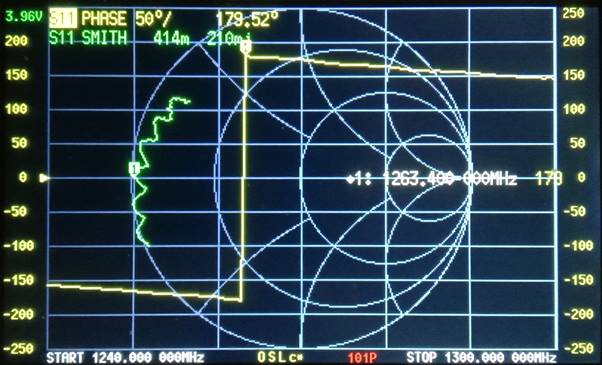
Photo 2.
The
NanoVNA S11 phase display (yellow trace) shows that at 1263.4 MHz
the phase reaches +180° (+179.52°). At slightly lower frequencies,
the display transitions to -180°, appearing as a vertical shift.
This indicates that the RG-6 coax is at an electrical quarter
wavelength or an odd multiple.
In this instance, the length
corresponds to approximately 5λ/4 (about 265 mm including
connectors and termination lugs).
The additional length between physical tested length and the
calculated length is in part the N connector and the lugs and tails
of the completed cable.
The display spans the 23 cm band from
1240 MHz to 1300 MHz. Across this range, the phase varies smoothly
between approximately -150° and +150°, indicating that the coaxial
transformer remains effective across the full band with maximum
efficiency at 1263.4 MHz.
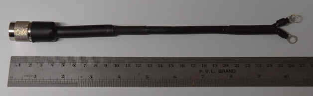
Photo 3.
The
completed quarter-wave
RG6 coaxial cable impedance transformer
Antenna
Matching (SWR and Smith)
With
the antenna is full assembles the SWR was measured with a short
length of 50ohm coax connected to the antenna with final
adjustment made by moving the antenna's reflector element for the
best SWR value.
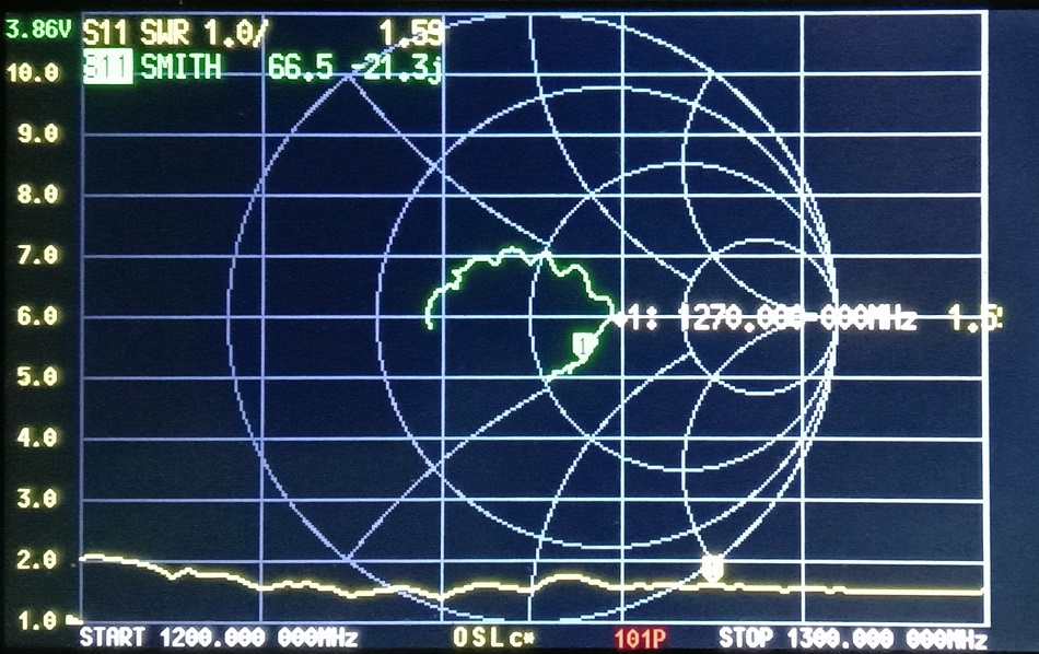
Photo 4.
The
NanoVNA SWR sweep from 1200MHz to 1300MHz
Construction
The
element mounting assembly shown in Figure 3 and Photo 7 consists of
a stainless steel hose clamp with a 5mm stud hole drilled in the
strap. A countersunk-headed set screw is then mounted with the flat
head against the boom, as depicted in Photo 7. The hose clamp stud
mount eliminates the need for drilling any holes into the boom and
allows for infinite lateral adjustment along the boom.
The element mounting bracket, as seen in Photo 7, 8, and 9, is made
of 12 x 12mm aluminium channel. This aluminium channel features a
'V'-cut notch that facilitates the attachment of elements of various
diameters. Additionally, a lower notch is cut out to ensure the
bracket mounts flat against the boom and remains clear of the hose
clamp strap. It is crucial to accurately cut the 'V' notch to
achieve symmetrical element mounting.

Figure
3 Element
to Boom mounting arrangement.
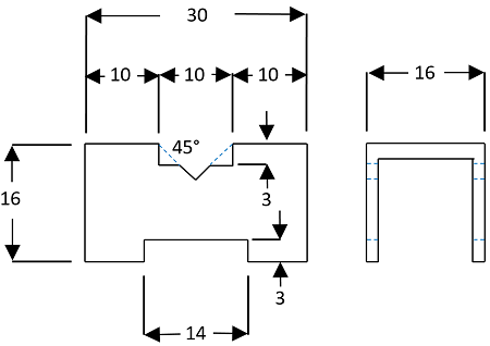
Figure
4 Details of the Element
to Boom mounting bracket. The
bracket allows either round elements or flat 10mm width x 3mm height
rectangular elements.
Yagi-Uda antenna dimension calculator
https://www.changpuak.ch/electronics/yagi_uda_antenna.php
JavaScript Version 12.01.2014, based
on Rothammel / DL6WU
TOP
OF PAGE
Page initiated 15 April,
2026
Page
last revised 15 April, 2026
|