Peter Miles
Northam, Western Australia QRZ Page: VK6YSF
Email
Social
Media
Buy me a coffee
If you found information on this site interesting, beneficial, or learned something new, please consider buying me a cup of coffee by clicking the coffee cup below.
It helps keep the website going and is greatly appreciated.
SKEW PLANAR PLAN ANTENNA
Skew Planar Plane Antenna
for 435MHz. October 2024.
The
skew-planar antenna was first introduced to the amateur radio
community by Robert H. Mellen, W1IJD, and Carl T. Milner, W1FVY, in
a 1963 QST article, yet it has received little attention
since then. The only other notable discussion in amateur radio
appeared in the November/December 2006 issue of TCA: The
Canadian Amateur, in an article by Graham Ide, VE3BYT, and
David Conn, VE3KL.http://www.ve3byt.com/SkewPlanarAntenna/
The
skew-planar antenna features a set of elements arranged in a tilted
or skewed plane, typically forming a triangular or rectangular
pattern. This configuration produces an efficient radiation pattern
with omnidirectional coverage, making it suitable for various
applications, including amateur radio, satellite communication, and
other wireless systems.
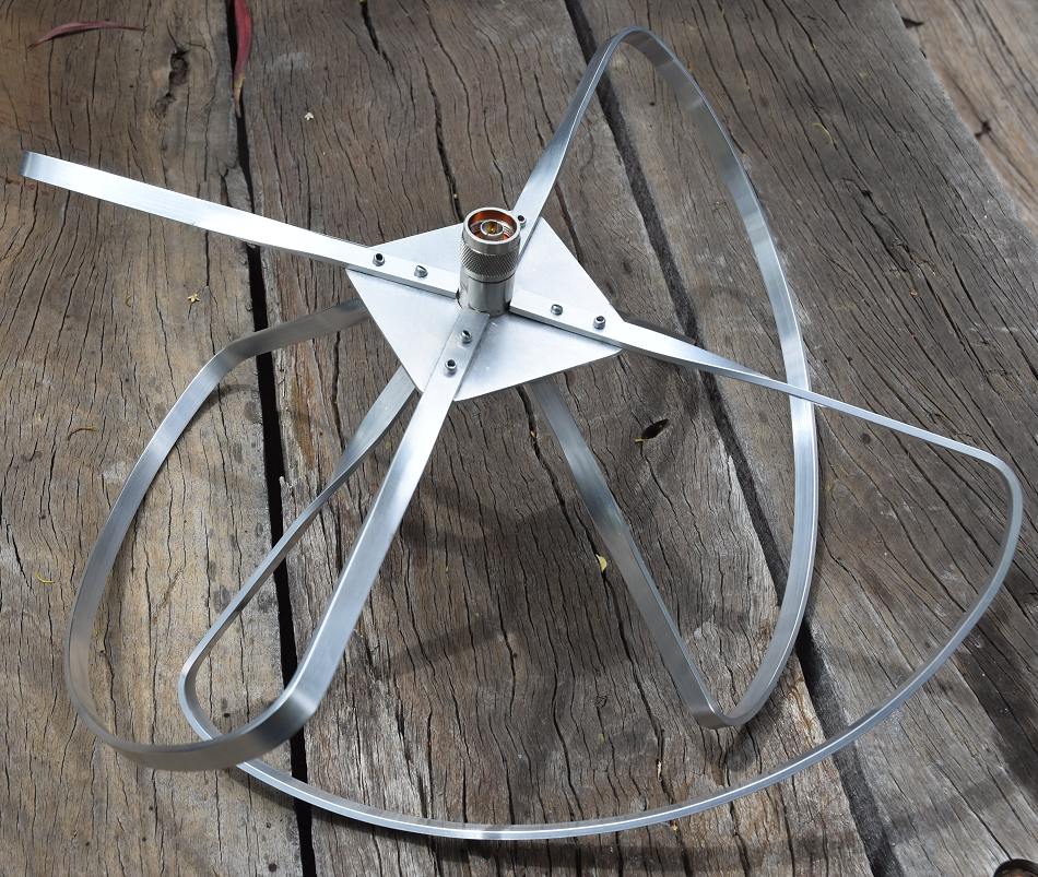
Photo
1. Skew-Planar Antenna assembled for testing.
The antenna
is especially popular among RC (Radio Control) enthusiasts, who use
it on aircraft due to its omnidirectional pattern and circular
polarization. Circular polarization helps maintain a stable signal
despite rapid changes in the aircraft's orientation, which is
crucial for reliable communication and video transmission in FPV
(First-Person View) set-ups. The circular polarization reduces signal
loss caused by cross-polarization issues with other antenna types, thus enhancing video
quality and consistency. For optimal performance, both the
transmitting and receiving antennas must use the same circular
polarization rotation—either right-hand or left-hand—to avoid
significant signal loss.
In amateur
radio, the skew-planar antenna's omnidirectional coverage and
circular polarization characteristics make it well-suited for Low
Earth Orbit (LEO) satellite operations. Its ability to maintain
consistent signal strength despite variations in satellite
orientation provides an advantage for reliable communication.
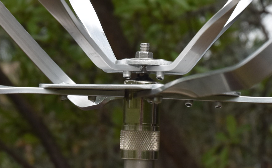
Photo
2. Top view of Skew-Planar Antenna showing the right-hand
rotation
Photo
3. Top view of Skew-Planar Antenna showing the element
attachments
Antenna
description
The antenna
is a 4-element skew-planar antenna for 438 MHz constructed from all
aluminium around a standard male N connector.
Frequency:
435Mhz
Polarization:
Circular
/ Right
Gain:
2
dBi
Approximately
VSWR:
Better
than 1.3:1 from 430 – 450MHz
Impedance:
48.8
+3.1j (At 440 MHz)
Wavelength:
690mm
Construction
The antenna is constructed around a standard male N connector with a
100mm square aluminium radial mounting plate with a 16mm centre hole
to attach to the N connector with the standard coax gland screw cap
as shown in Photo 4.
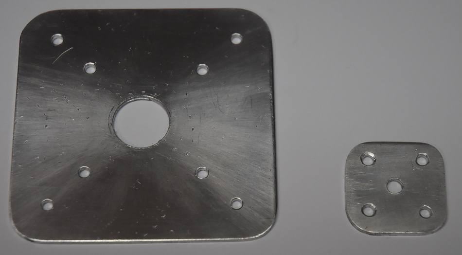
The elements have been attached with 3mm diameter pop-rivets to the
mounting disks
The smaller upper disk is fitted to a standard male N connector's
coax centre pin with a 6mm diameter stainless steel stud
as shown in Photo 5 and
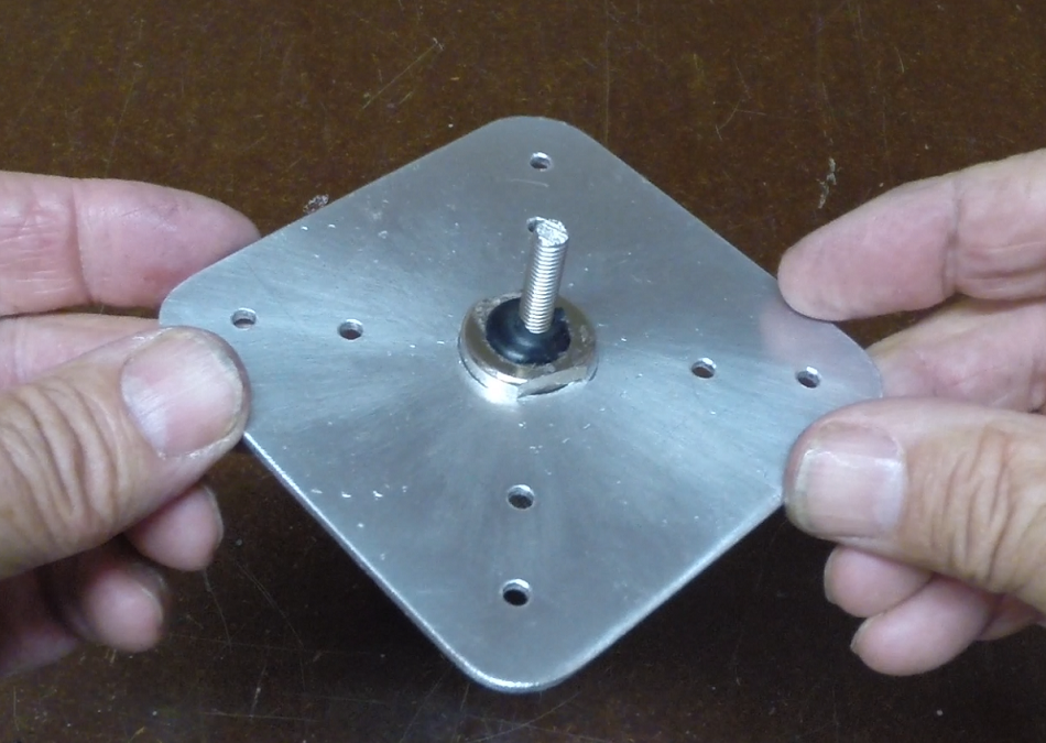
positioned in the N connector and secured with two part epoxy. A
small rubber grommet has been fashioned to fit tightly in the end of
the N connector body with a smearing of marine grade silicon to make
the assembly water proof.
Photo 6 shows the final assembly.
Photo 4.
Element attachment plates.
David
Conn (VE3KL)'s analysis of the Skew-Planar antenna confirmed that
the element lengths should be longer than a free-space wavelength at
the chosen design frequency by a factor of about 4.5 percent.
Note:I
have determined the factor as being 5.5%.
The
element lengths for various bands are shown in the below Table 1
for Fig 1.
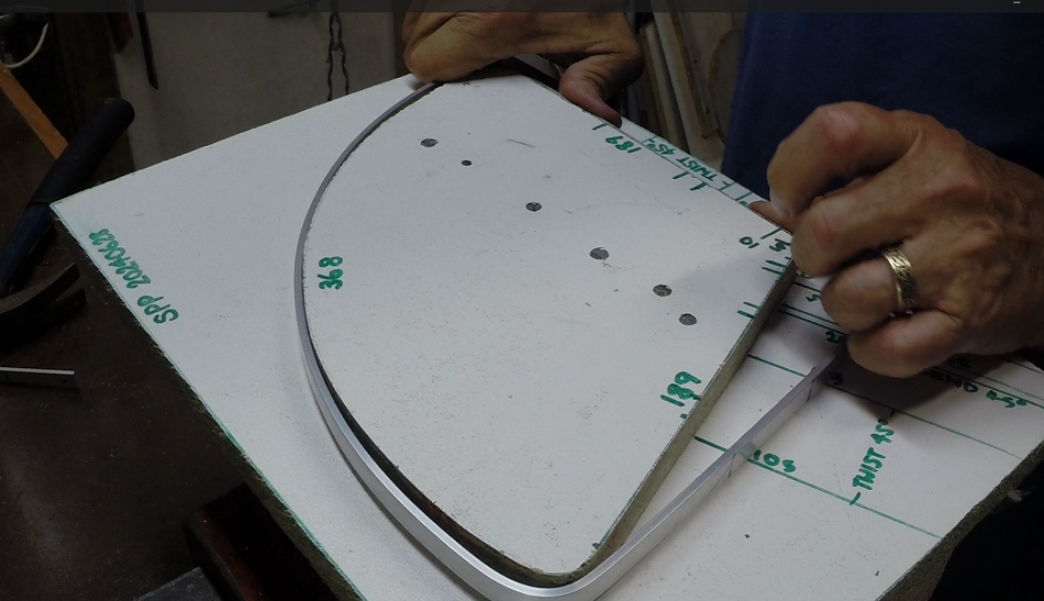
Each
element is shaped as shown in Figure 1 & 2 and in
Photos.On each end
of an element at the 1/4 length point, make a bend around a fairly
tight radius - for the 435 MHz antenna this was around a radius of
about 20mm.The half
element portion is curved out so that the straight 1/4 length
sections meet and form an angle with each other of about 100 to 110
degrees.If necessary,
adjust slightly the curvature where the one-quarter and the half
element lengths meet.
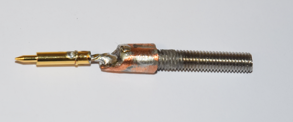
Photo 5.
Centre pin of the Male N connector soldered to the copper sleeve.
Copper sleeve Silvered Soldered to the 6mm stainless threaded
stud.
Photo 6.
N Connector, lower plate and threaded stud assemble.
Fig 1.
Element
layout. See Table 1 element lengths for various bands.
Table
1Dimensions for some
bands
Frequency
(MHz)
Wavelength
(mm)
(B)
1/2
Element Length
(mm)
(A)
1/4
Element Length
(mm) (Including attachment hardware)
Total
Element Length
(mm) (excluding attachment hardware)
430.0
698
368
184
736
435.0
690
363
182
728
440.0
682
360
180
720
Fig 2.
Antenna
general layout.
The antenna mounting is a standard antenna mirror mount bracket with
a female to female N connector bulkhead socket fitted for a range of
similar antennas that are constructed around male N connectors. See:
Generic
Antenna Mount.
Photo
7. Element being shaped.
Photo
8. Element angle rotation being shaped.
Adjustment
While the
Skew-Planar Antenna is quite forgiving due to its broadband
characteristics, there are limited opportunities for easy
adjustments to its elements. However, one useful adjustment is the
separation between the upper and lower attachment plates along the
threaded stud. This adjustment allows you to minimize SWR and tune
out any matching reactance
Photo 9.
Upper attachment plate allows some adjustment along the threaded
stud to minimise SWR
Antenna
testing
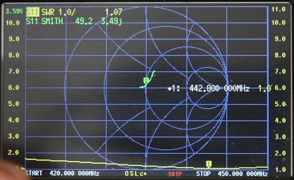
Photo 10. NanoVNA displaying
the antenna feed point SWR and Impedance.
The
antenna electrical matching characteristics were measured with a
NanoVNA and were recorded as a more than suitable SWR from 420 MHz to 450
MHz with a minimum or best match at approximately 443 MHz. The Smith
chart also indicated a near ideal impedance match of 49.2 +3.49j at
442.8 MHz.
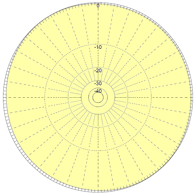
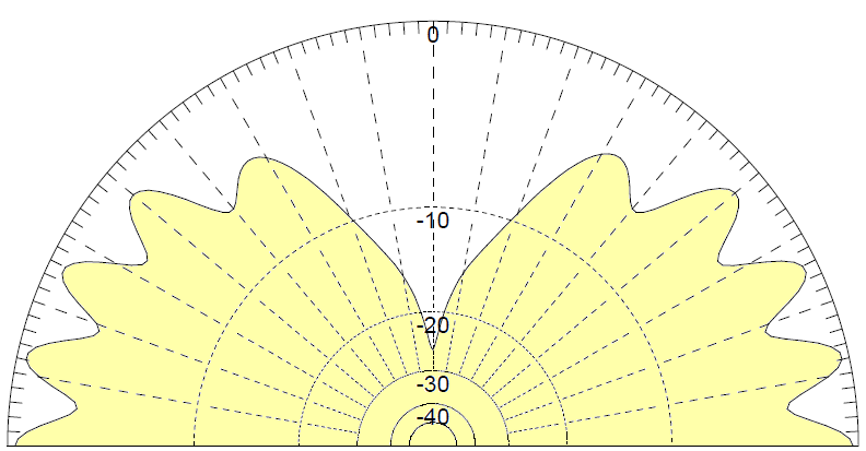
Modelling
Fig 3Azimuth and Elevation Radiation
pattern of theSkew
Planar Wheel Antennaat
438MHz.
MMANA-GAL
Antenna Analyser predicted the following results from the model.
Gain
: 5.71 dBi = 0 dB (Vertical polarization)
F/B:
-0.19 dB; Rear: Azim. 120 dg, Elev. 60 dg
Freq:
438.000 MHz
Z:
58.186 + j6.409 Ohm
SWR:
1.2 (50.0 Ohm),
Elev: 0.0
dg (Perfect GND :1.50 m height) Based on that the antenna is likely
to be mounted over a steel roof.
Fig 4
A three dimensional view of the radiation pattern of the Skew Planar
Plane Antenna at
438MHz. Radiation plot was produced by MMANA-GAL Antenna Analyser software.
Antenna
Gain Range Testing
This
is the most important antenna measurement because even if all other
measurements such as SWR and resonance are satisfactory, however if
the antenna fails to achieve at least an approximation of the desired
or predicted gain, it can be considered a failure. Measuring antenna
gain is perhaps one of the most challenging tasks to accomplish
successfully, as it requires a large and unobstructed area, especially
free from metallic obstacles that can significantly distort the
antenna's ideal radiation pattern. Figure 5 below illustrates an
example of an antenna gain range test using the NanoVNA.
Fig 5Shows
the basic antenna gain range test set-up.
Figure
4shows
the basic set up with d indicating
the distance between the Source dipole antenna and the Reference
dipole antenna and while not critical needs to be between 2 and 3
wavelengths apart. In the set up the two antennas were placed
2mtr (approximately 3 wavelengths) apart.
The
ideal separation for antenna gain testing depends on various factors
such as the frequency of operation, the type of antennas being tested,
and the testing environment. Generally, a separation of at least 2-3
wavelengths is recommended between the transmitting and receiving
antennas to minimize interference and achieve accurate measurements.
Larger antenna separations can give false readings due to ground
reflection and other multi-path effects.
The
suitable height above ground for antenna gain testing depends on
various factors, including the type of antenna, the desired testing
accuracy, the operating frequency, and the testing environment. As a
general guideline, a height of at least 1 to 2 wavelengths above
ground is recommended to minimize ground effects and reflections.
The
antennas in this set-up are positioned 1.5 meters above the ground,
which is slightly over 2 wavelengths at 435 MHz.
Source
Antenna is
a 435MHz Source dipole antenna.
Reference
Antenna is
also a 435MHz Reference dipole antenna. A measurement will be taken
with this antenna to determine the base line. This antenna is replaced
with the Skew Planar Plane Antenna
and the return loss measured that will
show the gain/los in dB with respect to the Reference dipole antenna.
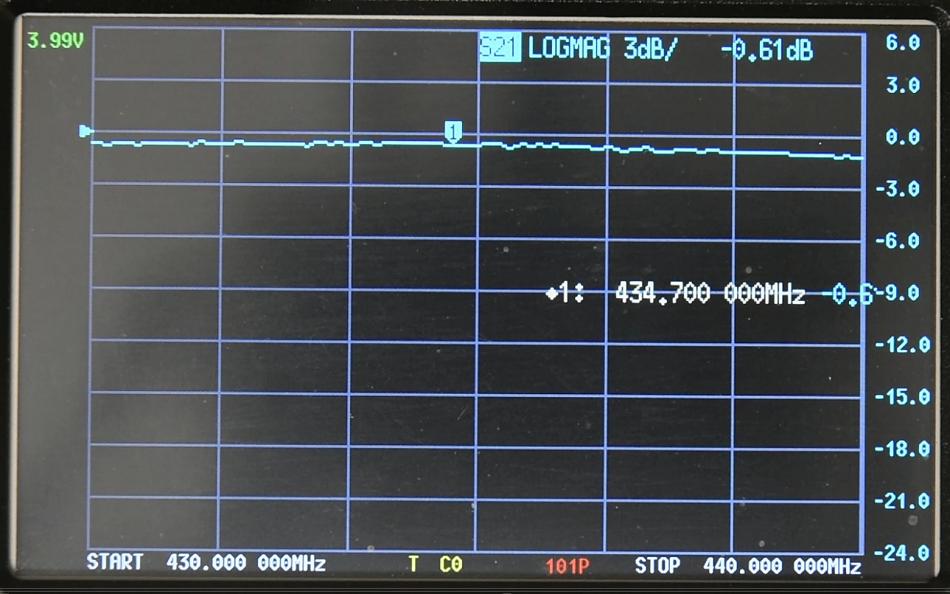
NanoVNA set
to LOGMAG with a display of -24 ~ +6dB and
calibrated to remove the lead characteristics from the measurements
and with the reference antenna and set the base line to 0 as per Fig
4.
Photo
11 NanoVNA
showing the Fig 5 set-up and calibrated for the base line to be zero.
The
first test was to rotate the reference dipole 90° for cross
polarization measurement to benchmark cross polarization immunity of
the Skew Planar Plane Antenna. With the reference dipole
rotated at 90°
to the source dipole a path
loss of approximately -28dB was recorded.
Photo
12 NanoVNA
showing the Fig 5 set-up with the reference dipole rotated 90° for
cross polarization measurement.
Fig 6 Shows
the basic antenna gain range test set-up with the antenna under test
in place.
Target
performance.
The
expectation is that the Skew Planar
Plane Antenna
will have a high degree of cross polarization immunity from high
path loss and that the antenna a more or less all of sky view.
Test
Results.
The
Skew Planar Plane Antenna
was tilted in a range form 0.0°
to 90° in 5° to 10° increments and with source antenna polarization
changed by 90°
for each tilt angle.
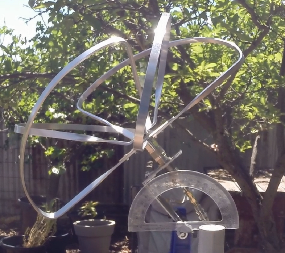
Photo
13 The
Skew Planar Plane Antenna set up at 45°
angle
Antenna
Under Test
Reference
Dipole Polarization and path gain/loss
Tilt
Angle
Horizontal
dBb
Vertical
dBb
0
-8.0
-7.4
5
-8.0
-6.7
10
-6.8
-5.7
15
-5.0
-5.0
20
-4.1
-4.2
25
-3.5
-4.2
30
-2.8
-3.8
35
-2.7
-3.2
45
-1.4
-2.0
55
-2.0
-1.8
60
-2.1
-1.0
70
-3.5
-1.0
80
-5.2
-2.0
90
-18.5
-3.6
Table
1 Recorded data from Skew Planar Plan Antenna range testing.
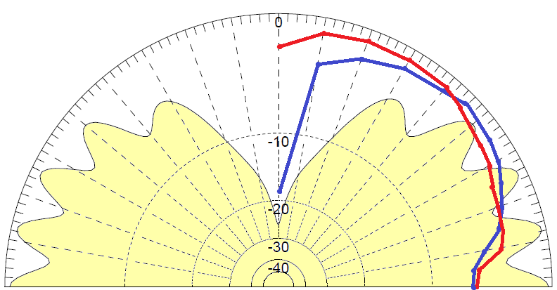
Fig 7 Shows
range testing data overlayed on the MMANA model's predicted
slice radiation pattern.
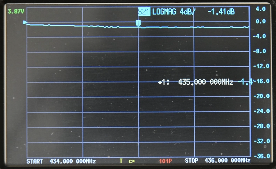
Photo
12 NanoVNA
showing the Fig 5 set-up and displaying
Skew Planar Wheel Antenna
at 45 with the gain
compared with the reference dipole antenna.
Conclusion
The range test of the Skew Planar
Plane Antenna confirmed that its performance closely matches the
MMANA-GAL model. The antenna demonstrates strong immunity to path
losses due to cross-polarization. Except for directly above the
antenna, the radiation pattern is generally uniform and, again,
closely aligns with the model.
It is important to note that there are
trade-offs: achieving a more omnidirectional radiation pattern and
immunity to cross-polarization losses comes at the cost of a gain
reduction of approximately -1 to -8 dBd compared to a reference
dipole.
The antenna, as used by model aircraft
enthusiasts in the 2.4 GHz and 5.8 GHz bands for FPV (First Person
Video), is well suited for this purpose and may also be beneficial
for LEO (Low Earth Orbiting) amateur satellite
communication-particularly on the uplink, where additional power can
compensate for the slight loss in gain.