|
SKEW PLANAR WHEEL
ANTENNA
Skew
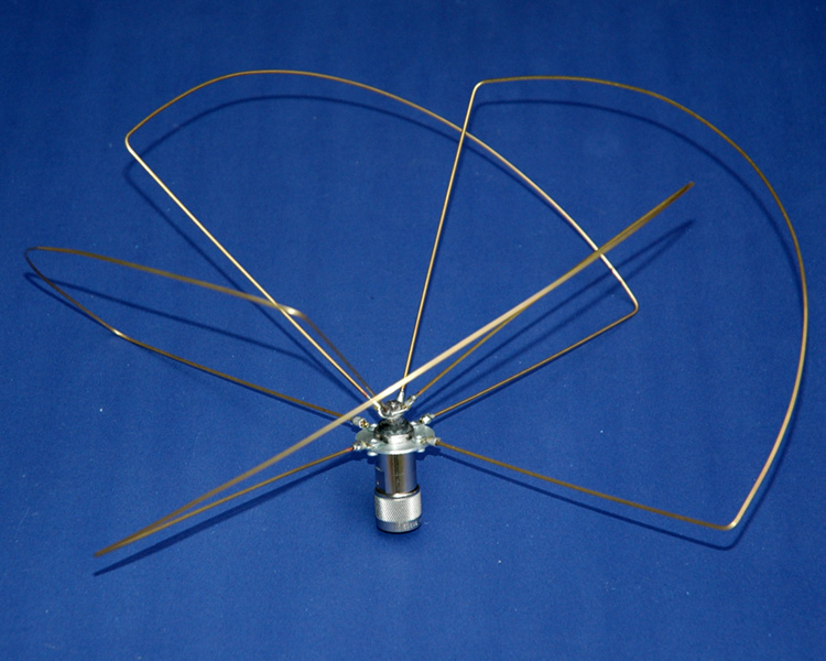
Planar Wheel Antenna for 435MHz. November 2012.
Skew-Planar
antenna has had little attention in the amateur radio community
despite being present in QST by Robert H. Mellen, W1IJD, and Carl T.
Milner, W1FVY in late 1963. The only other information of this antenna
relating to amateur radio is an article published
in the November/December 2006 issue of TCA, The Canadian Amateur
magazine by Graham Ide, VE3BYT, with David Conn, VE3KL.
The
popular usage of the Skew-Planar antenna appears to be RC (Radio
Control) enthusiasts as an ideal aircraft antenna due to its
omnidirectional and circularly polarization. The
low omnidirectional pattern and the circularly polarization
characteristics of this antenna should also be suitability for LEO
(Low Earth Orbiting) satellite operations.
|

|
|
Photo 1
Skew
Planar Wheel Antenna for 435MHz completed assembly.
|
Construction
Skew-Planar
antenna constructed around a standard male N connector is favoured
format for many of my VHF and UHF antennas as it facilitates easy
antenna change over. See:
Generic
Antenna Mount.
|

|
|
Figure 1 Antenna
general layout.
|
Referring
to Photo 1 and Figure 1, showing how everything fits
together. The elements
are assembled on the hub with the long section of each element (the
half element length part) at 45 degrees to the horizontal, for
right-hand circular polarization slanted up to the right when you are
looking at the closest element. The
upper end of each element goes into the lug on the top stack at 100 -
110 degrees counter clockwise from its lug on the bottom stack.
|

|
|
Figure 2 Element
layout. See Table 1 element lengths for various bands.
|
Skew-Planar
antenna constructed around a standard male N connector and a 33mm
diameter aluminium radial mounting disk with a 15mm centre hole for
attachment to the N connector with the standard coax gland screw cap.
The four radiating loop elements have been attached to the radial
mounting disk with tinned crimp lugs and 2mm diameter pop-rivets. The
other end of the loop is attached to the centre N connector pin which
has a stainless steel screw thread sleeved to the pin and each of the
elements have crimp lugs with attached atop of each other to the screw
tread.
The
screw tread is fitted to a standard male N connector's coax centre pin
and positioned in the N connector and secured with two part epoxy. A
small rubber grommet has been fashioned to fit tightly in the end of
the N connector body with a smearing of marine grade silicon to ensure
the assembly is water proof.
See Photo 1 and Fig 3.
David Conn (VE3KL)'s analysis of the Skew-Planar antenna
confirmed that the element lengths should be longer than a free-space
wavelength at the chosen design frequency by a factor of about 4.5
percent. element lengths for various bands are shown in the
below Table 1 for Fig 2.
Each
element is shaped as shown in Figure 1 & 2 and in Photos
1. On each end of an
element at the 1/4 length point, make a bend around a fairly tight
radius - for the 435 MHz antenna this was around a radius of about
10mm. The half element
portion is curved out so that the straight 1/4 length sections meet
and form an angle with each other of about 100 to 110 degrees.
If necessary, adjust slightly the curvature where the
one-quarter and the half element lengths meet.
Table
1 Dimensions for some
bands
|
Frequency (MHz) |
Wavelength
(mm)
|
(B)
1/2
Element Length
(mm)
|
(A)
1/4
Element Length
(mm) (Including attachment hardware)
|
|
145.5
|
2062
|
1077
|
539
|
|
222.0
|
1351
|
706
|
353
|
|
435.0
|
690
|
360
|
180
|
|
915.0
|
328
|
171
|
86
|
|
1296.0
|
233
|
122
|
61
|
|
2401.0
|
125
|
65
|
33
|
Table
of Skew-Planar antenna element dimensions for various local Australian
and some international amateur radio bands.
|

|

|
|
Photo
2 'N' Connector element hub
|
Figure
3 'N' Connector element hub
|
|

|
|
Figure 4 Radial
element mounting disk
|
The antenna mounting is a
standard antenna mirror mount bracket with a female to female N
connector bulkhead socket fitted. See:
Generic
Antenna Mount.
|

|
|
Figure
5 A
three dimensional view of the radiation pattern of the Skew
Planar Wheel Antenna at
435MHz. Radiation
plot was produced by MMANA-GAL Antenna Analyser software.
|
|

|
|
Figure
6
Azimuth and Elevation Radiation pattern of the Skew
Planar Wheel Antenna at
435MHz.
|
MMANA-GAL Antenna Analyser
predicted the following results from the model.
Gain:
5.75dBi = 0dB (Vertical polarization)
Freq:
435.00MHz
Z:
45.411 - j24.294Ohms
SWR: 1.7
(50.0 Ohms)

Figure 6
Skew
Planar Wheel Antenna SWR 420MHz to 480MHz
Details of the generic antenna mount.
See: Generic
Antenna Mount.
References
A brief description of the Skew-Planar
Wheel Antenna see:
http://www.ve3byt.com/SkewPlanarAntenna/
The
above radiation plots were produced using MMANA-GAL Antenna Analyser
software by JE3HHT, Makoto (Mako) Mori at http://hamsoft.ca/
TOP
OF PAGE
Page
last revised 12 March 2022
|