|
TRANSVERTER FOR THE
630MTR BAND
630M band (472kHz-479kHz) Transverter.
Under
development
The
630M band offers some real technical challenges with such a long
wavelength coupled with very restrictive ERP (Effective Radiated
Power) limits, it is never the less a band worthy of exploration. In Australia and this is not the case in some
other country's the licence conditions permit the use of any mode with a maximum bandwidth of 2.1 kHz.
While most communication within this band is CW or one of the many narrow
band digital modes there is the tantalizing option of SSB voice contacts
and it is with this view that the transverter design is for linear
conversion allowing for all possible modes that fit within the 2.1kHz
bandwidth to be utilised.
The
design for the 630 metre band transverter is based on using the 30
metre amateur band as the transmit and receive IF as some modern commercial amateur radio HF transceivers
including my TS930 the coverage of this band for both transmit and receive is from 10.0MHz
to 10.5MHz. This allows the transverter to mix a 10.0MHz local oscillator
with the transceiver tuned to 10.472MHz giving an out or input at
0.472MHz or 472kHz.
The
five key sections of the transverter, the 10MHz Local oscillator, the
Receive Converter, the Transmit Converter, final common low pass
filter and the Transverter
Switching circuit have been constructed on five separate boards with the view
that each of the individual sections can be upgraded with improved
future designs.

Fig 1
Block diagram for the 630M band (472kHz-479kHz) Transverter. This is
subject to further development.

Photo 1
Front top view of the assembled 630M band (472kHz-479kHz)
Transverter.
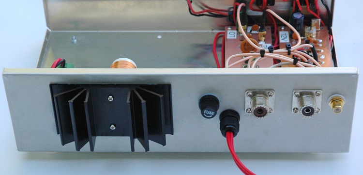
Photo
2 Rear top view of the assembled 630M band (472kHz-479kHz)
Transverter.

Photo
3 Top view of the assembled 630M band (472kHz-479kHz) Transverter.
TOP
OF PAGE
Page
last revised 12 March 2022
|