|
MULTI-BAND HF INVERTED L ANTENNA
Mult-band
HF
portable Inverted L antenna - 7 MHz to 30MHz. October 2025. Under
development
Requiring
an easily deployable and reliable antenna for portable campsite
radio communication, I selected a multi-band inverted L radiator with
a 4m counterpoise type radials. This type of antenna offers
reliable and predictable performance while maintaining a small
set-up footprint. The inverted L antenna uses 13 meter-long
elements, covering a frequency range from 7 MHz to 30 MHz with reasonable efficiency and a
low radiation angle.
The
multi-band inverted L antenna is intentionally designed not to be
resonant on any amateur band, resulting in a relatively high
feed-point impedance across all intended operating frequencies. The
antenna is fed through both a 4:1 balun and a 1:1 choking balun. A
length of coaxial cable then connects the system to the antenna
matching unit and SWR meter before finally reaching the transceiver.
The
4:1 balun is used to transform the higher antenna feed-point
impedance to a level that the matching unit can more easily manage
and reduce the higher SWR levels on the connecting coax feed-line.
The 1:1 choking balun is employed to suppress common-mode RF
currents that might otherwise radiate from the coax and compromise
the antenna’s intended radiation pattern and interfere with other
equipment..
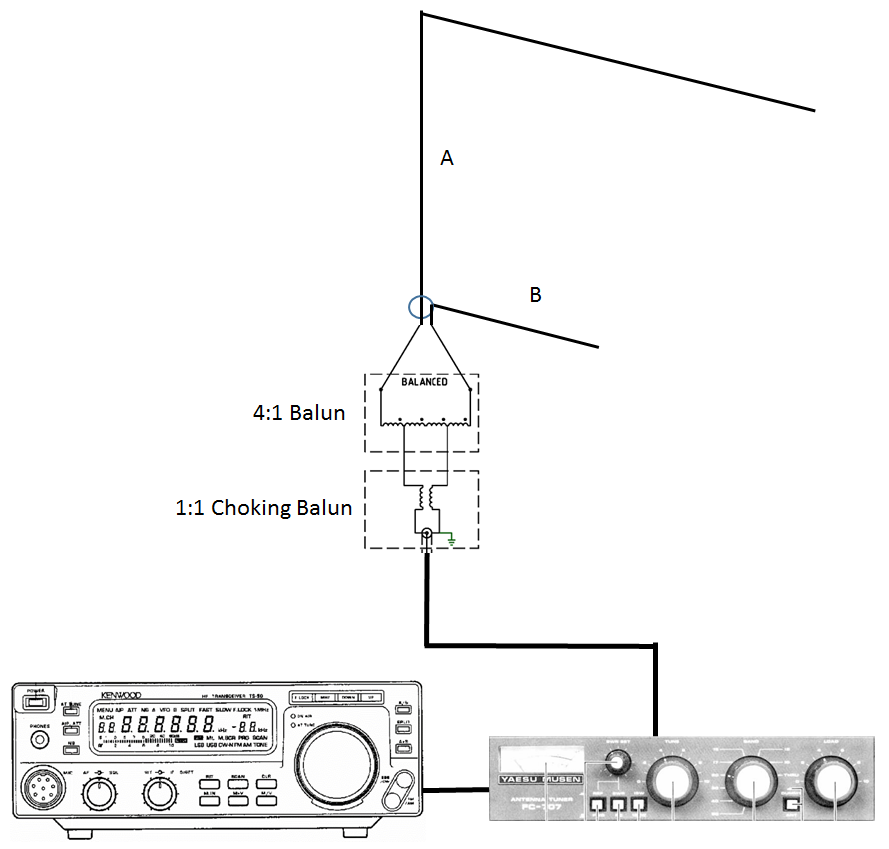
Fig
1
Shown is the complete portable set up. The antenna's 13m (6m + 7m)
Inverted L element (A), the three 6.2m ground-plane radial elements (B), the
4:1 + 1:1 balun hub, 50 Ohm coax cable, antenna matching tuner and
the TS-50 radio.
Below
is an MMANA-GAL antenna model prediction for antenna load
characteristics across the HF band from 7MHz to 30MHz for connection
impedance of 200 ohms and by avoiding the high SWR levels for the
intended amateur bands the systemis within the matching range of the
antenna matching tuner. The model shows the load SWR for
a direct 1:1 balun, a 4:1 balun and a 9:1 balun match.
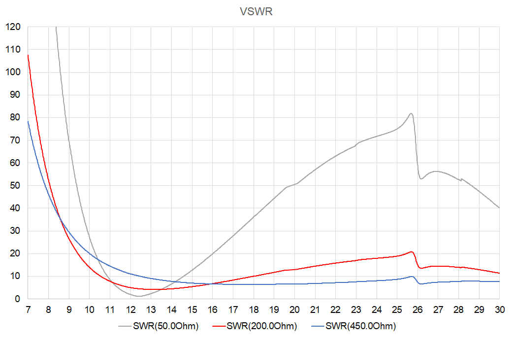
Figure
2 MMANA-GAL antenna
model prediction
of the antenna SWR
through a 1:1 Balun (50 Ohm Impedance) and through a 4:1 Balun (200
Ohm Impedance) plus 1:1 balun combination to achieve an easier
broadband match and reduce coax cable losses. The vertical axis is
the SWR ratio and the horizontal axis is the frequency in MHz. The
antenna is mounted to a Squid pole with the
feed point being approximately 1.5m above the ground. Also shown is a
9:1 Balun (450
Ohm Impedance) connection that indicates an improved SWR on the coax
feed-line for 7 MHz and frequencies above 16 MHz.
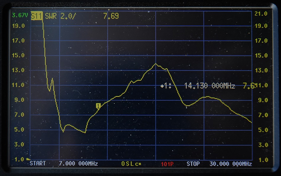
Figure
3 NanoVNA showing the SWR as presented
at the 4:1 and 1:1 combination balun. While broadly similar to the
MMANA predicted SWR values it appears to be a little better.
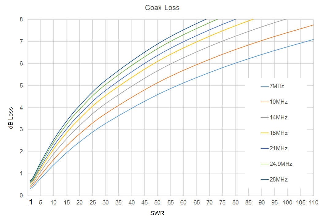
Figure
4 Chart
shows coax line losses (Vertical axis) for a 10m length of coax at
various frequencies at various SWR ratios (Horizontal axis). This
chart highlights the importance of a step down balun transformer in
reducing the SWR losses on the coax feed-line and where possible in using
the minimum length of coax
feed-line.
|
RG58 Coax Lengths @ SWR 15:1 |
| Frequency |
2 |
4 |
6 |
8 |
10 |
12 |
15 |
| 7 |
0.438 |
0.836 |
1.202 |
1.54 |
1.855 |
2.149 |
2.149 |
| 14 |
0.614 |
1.153 |
1.634 |
1.634 |
2.466 |
2.831 |
3.33 |
| 28 |
0.858 |
1.577 |
2.197 |
2.742 |
3.23 |
3.672 |
4.267 |
Figure
5 Chart
shows coax feedline losses in dB for various lengths of RG58 coax at
7, 14 and 28 MHz. Ideally this should be kept under 2.0 dB. Note
that around 3 dB about half the power is lost and this is not
including balun and tuner minor losses.
Construction
The
Mult-band
HF
portable inverted
L antenna
is simply a main radiator 13m
in length made from PVC covered 0.75mm2
(AWG 18/19) copper wire. The counterpoise element is 4m in
length from the same material. The antenna elements have attachment loops at the ends and all
wires have crimp lugs for connection to the balun hub.
The
4:1
Balun Hub is the convenient central hub of the
wire ground plane antenna. The dimension are dictated by the the
height of the support structure, a 7m Squid pole, not be a resonant
length at any amateur band and not being too long at the 10m band as
to produce a high angle of radiation.

Photo
1 Shown is the 4:1
Balun Hub for the
wire ground plane antenna. The radiator wire element is attached to
the left post and the three radiators are attached to the right
binding post.
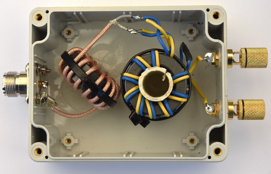
Photo
2 Antenna Balun assembly
See
Balun details: 4:1
Balun Hub that includes a 4:1 transformer plus a 1:1 choke balun
to mitigate common mode RF currents from the coax feedline.
|
|

|
|
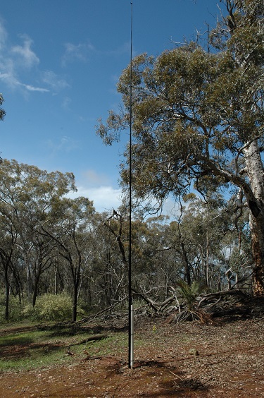
Photo
3 Squid pole
assembled in the field
|
Photo
4 Squid pole mounting arrangement.
|
Testing
and Modelling
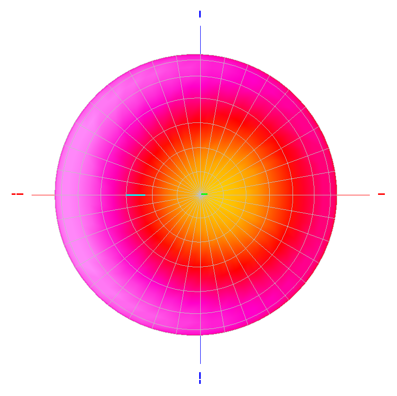
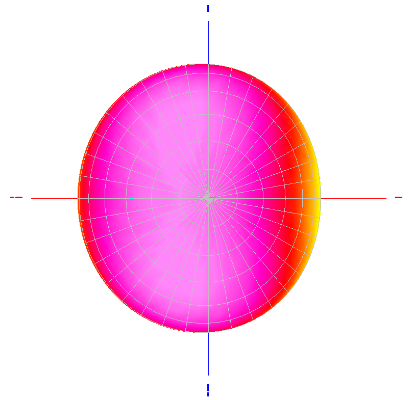
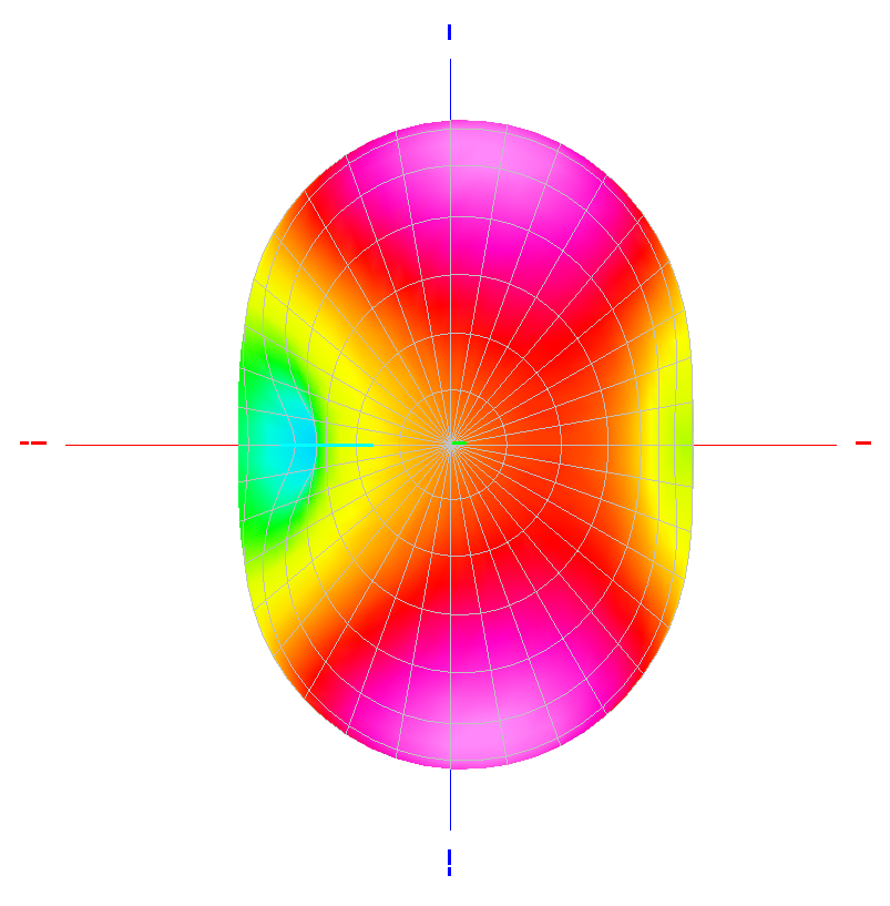
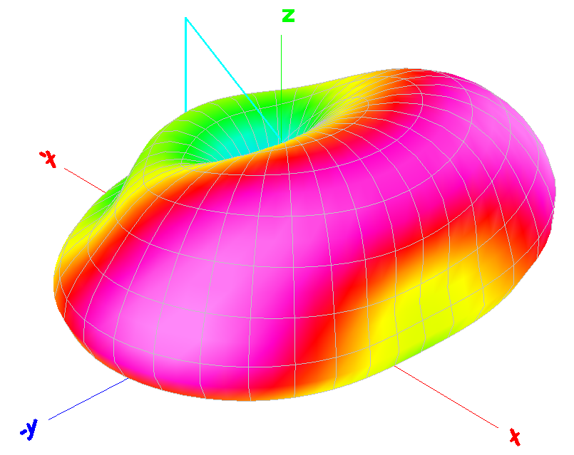
Figure
6 MMANA
antenna model
indicating uniform low angled radiation pattern at 40m.
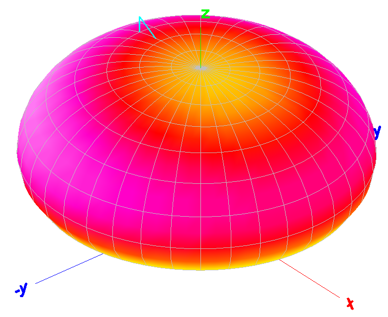
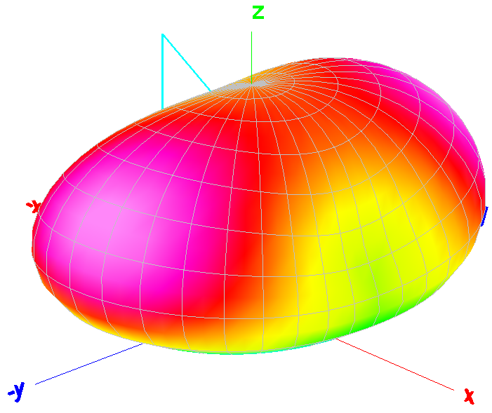
Figure
6 MMANA 3D antenna model
indicating uniform low angled radiation pattern at 40m.
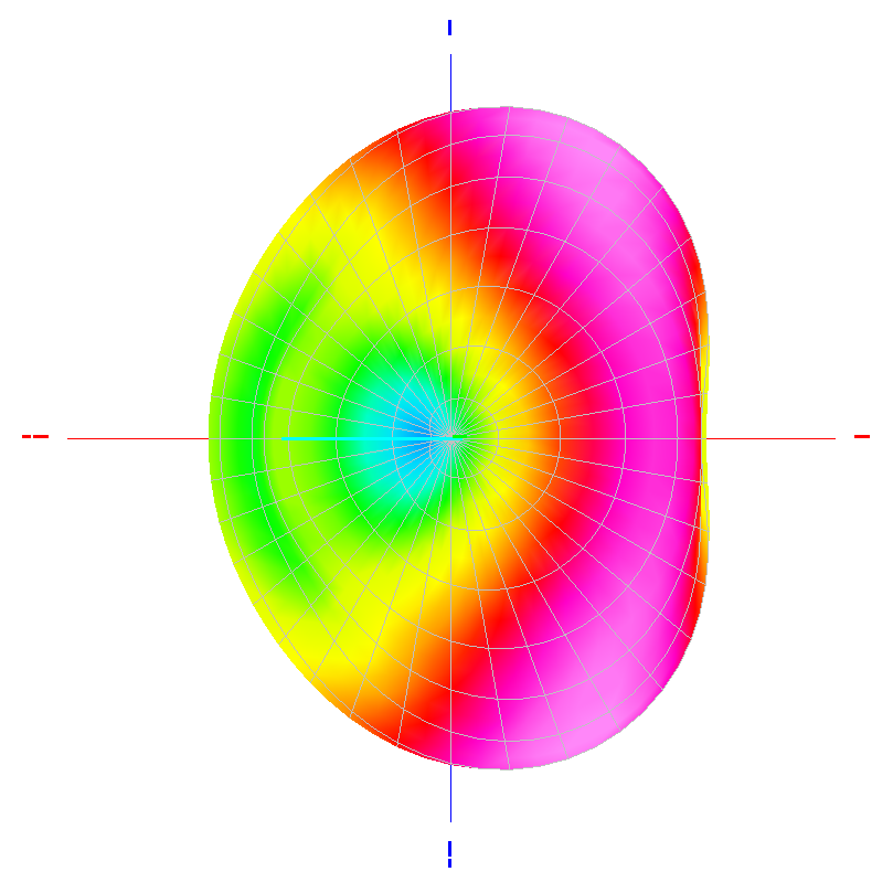
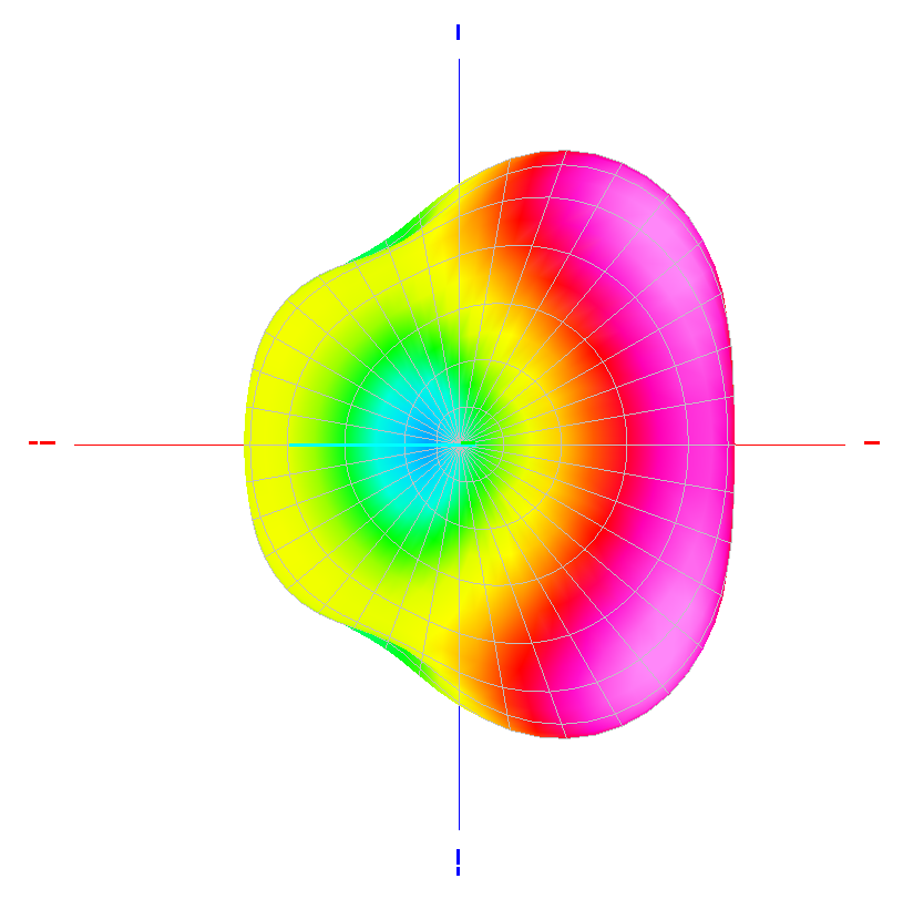
Figure
6 MMANA
antenna model
indicating uniform low angled radiation pattern at 30m.
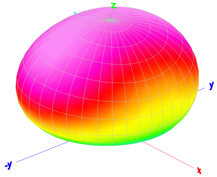
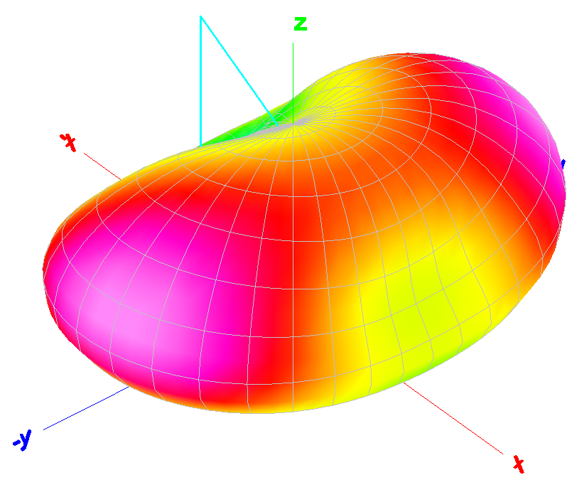
Figure
6 MMANA 3D
antenna model
indicating uniform low angled radiation pattern at 30m.
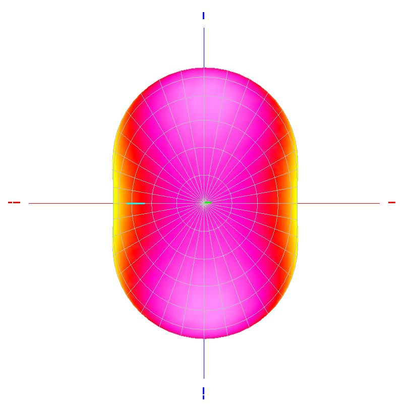
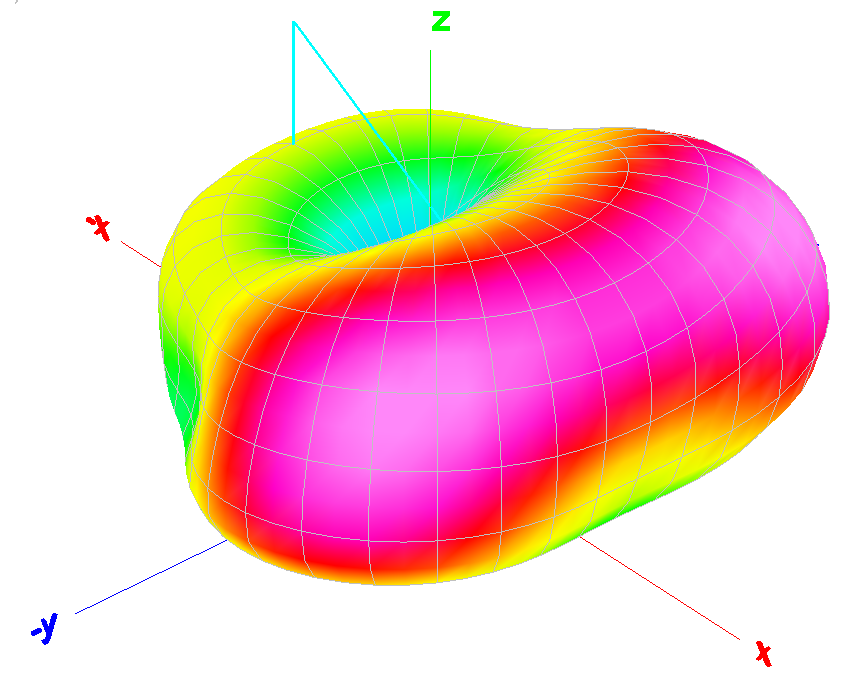
Figure
6 MMANA
antenna model
indicating uniform low angled radiation pattern at 20m.
Figure
6 MMANA 3D
antenna model
indicating uniform low angled radiation pattern at 20m.
Figure
6 MMANA
antenna model
indicating uniform low angled radiation pattern at 17m.
Figure
6 MMANA 3D
antenna model
indicating uniform low angled radiation pattern at 17m.

Figure
6 MMANA
antenna model
indicating uniform low angled radiation pattern at 15m.
Figure
6 MMANA 3D
antenna model
indicating uniform low angled radiation pattern at 15m.
Figure
6 MMANA
antenna model
indicating uniform low angled radiation pattern at 12m.
Figure
6 MMANA 3D
antenna model
indicating uniform low angled radiation pattern at 12m.
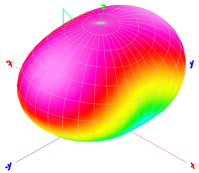
Figure
6 MMANA
antenna model still
indicating uniform low angled radiation pattern, however higher angle bulge
developing at 10m.
Figure
6 MMANA 3D
antenna model still indicating uniform low angled radiation pattern,
however higher angle bulge developing at 10m.
Operational
notes
The antenna has been set up at several locations and has shown consistent performance, with predictable matching at each site. On the 40m band, the antenna demonstrated meaningful capability by reliably connecting to a Winlink gateway approximately 200 km away.
References
American Radio Relay League. (1974). The ARRL Antenna Book. Newington, CT: ARRL.
Makoto Mori. (n.d.). MMANA-GAL antenna modelling software. Retrieved from
https://hamsoft.ca/pages/mmana-gal.php
TOP
OF PAGE
Page initiated 03 September, 2025
Page
last revised 27 January, 2026
|