|
HF FEED-LINE
INTERFACE CHOKE
AND 1:4 BALUN
HF
ladder feed-line and other multi-band HF antennas to coaxial cable choke and 1:4 balun.
(1.0MHz - 30MHz) connections.
To
connect various low powered potable balanced multi-band antennas with a sort length of coax
to a antenna match tuner and then to the radio a interface impedance
balun is used. The
un-balanced coaxial cable is connected to the balanced feed line
with the combination of a 1:1 choking balun and a 1:4 impedance step up
balun connected in series.
The antenna, feed lines, balun and antenna set-up is shown in below in
Fig 1 however the ladder line may forgone and the
interface
balun
connected directly to the antenna. Also various
balanced multi-band antennas
are intended for portable setups.
The
1:1 choking balun is to mitigate common mode RF currents on the coax
cable, reduces noise pickup on the coax from
entering the antenna system and also produce a balanced antenna system
that will have a more predictable radiation pattern .
The 1:4 impedance step up balun is
included to more broadly match the range of impedance at the
antenna/feed line with the nominal 50-ohm impedance of the coax.
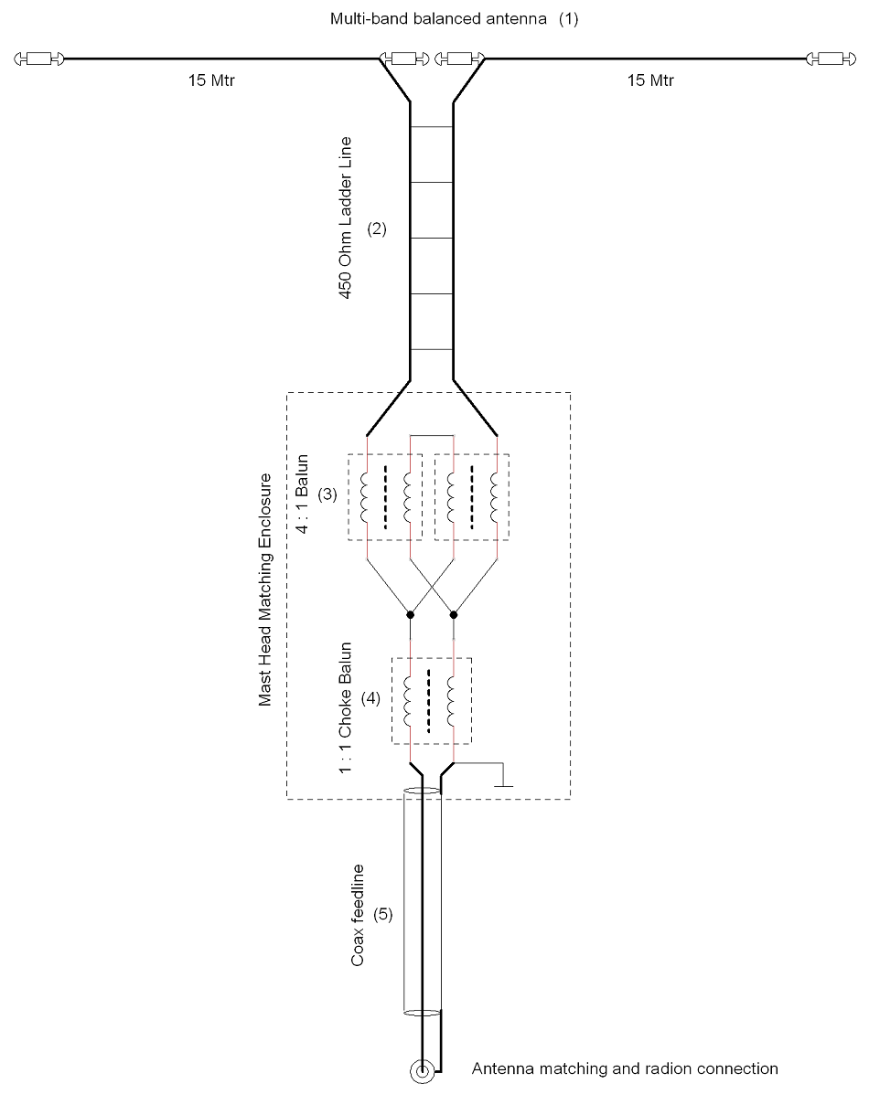
Figure
1 Multi-band
Doublet, feed-lines and balun configuration.
Basic
Multi-band Doublet Arrangement.
(1)
Inverted 'V' Dipole. (30Mtr total length) or other multi-band
balanced antennas.
(2)
450 Ohm Ladder Line. (May be omitted and directly connected to
the antenna).
(3)
1:4 Current Balun. See Fig 2 and 3 for details
(4)
1:1 Choking Balun. See Fig 4 for details
(5)
RG58 Coax cable (10m)
1:4
Current Balun
The 1:4 current balun is derived from two 1:1 current baluns with each consisting of a close double bifilar winding of 3.5 turns wound evenly spaced around
two FT140-43 Ferrite Toroid Cores. The wire is PVC covered copper wire, of 1.0mm diameter (AWG
18).
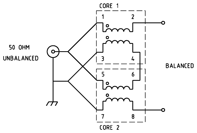
Figure
2 Schematic
of the 1:4 Guanella Current balun
.

Figure
3 Wiring
of the 1:4 Guanella Current balun.
|
Type
|
Impedance
transformation
|
|
Ratio
|
1:4
|
|
Frequency
Range
|
1.0
~ 60MHz
|
|
Core
Used
|
FT140-43
Ferrite Toroid Core x 2
|
|
Number
of turns
|
Core 1 =
7.5
turns x 2, Core 7 = 4.5 turns x 2. 1.0mm, AWG 18, PVC
covered wire |
|
SWR
|
1.2:1
or less. Ref: Photo 2
|
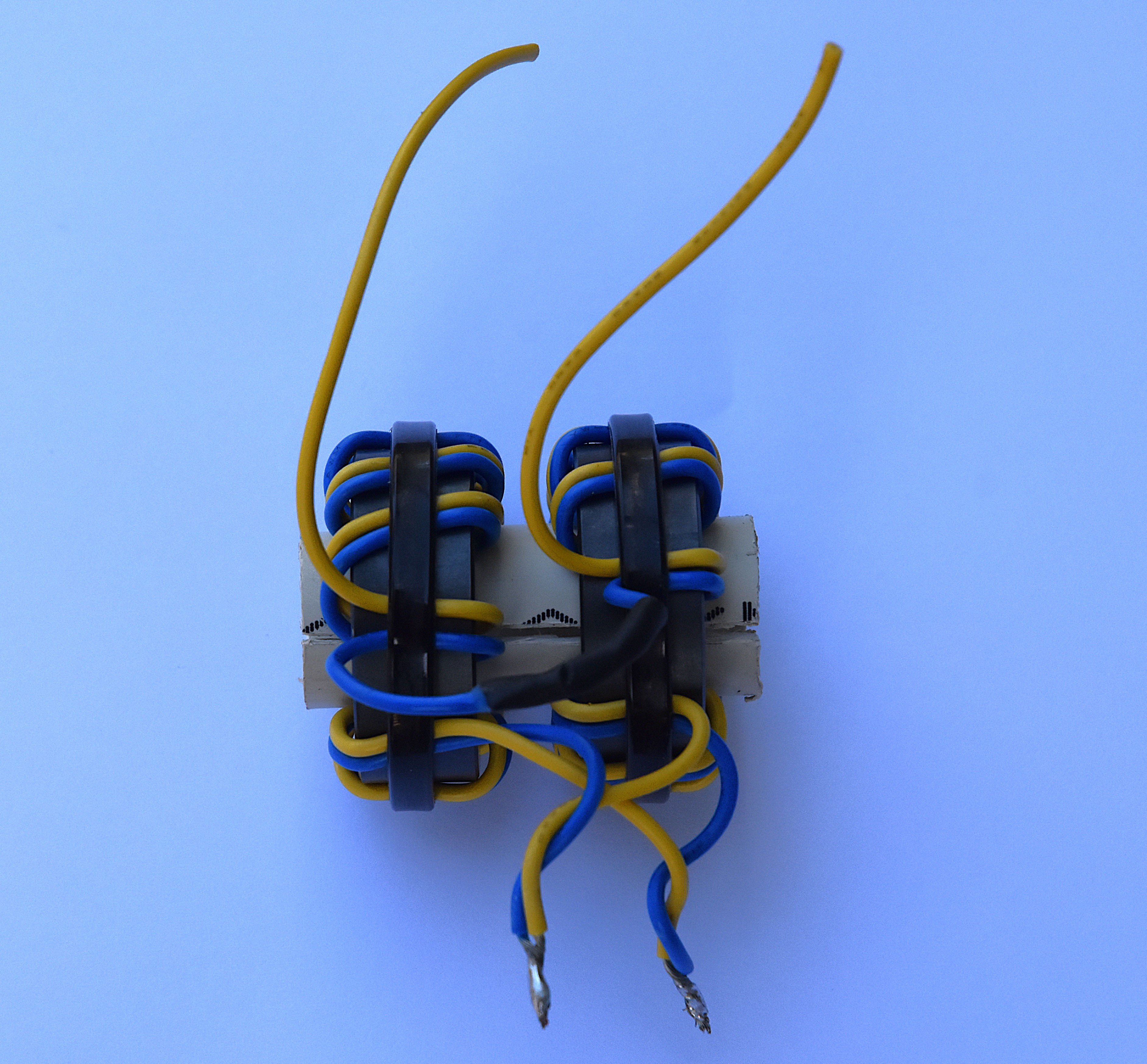
Photo
1 1:4
balun assembled.
1:4
balun testing
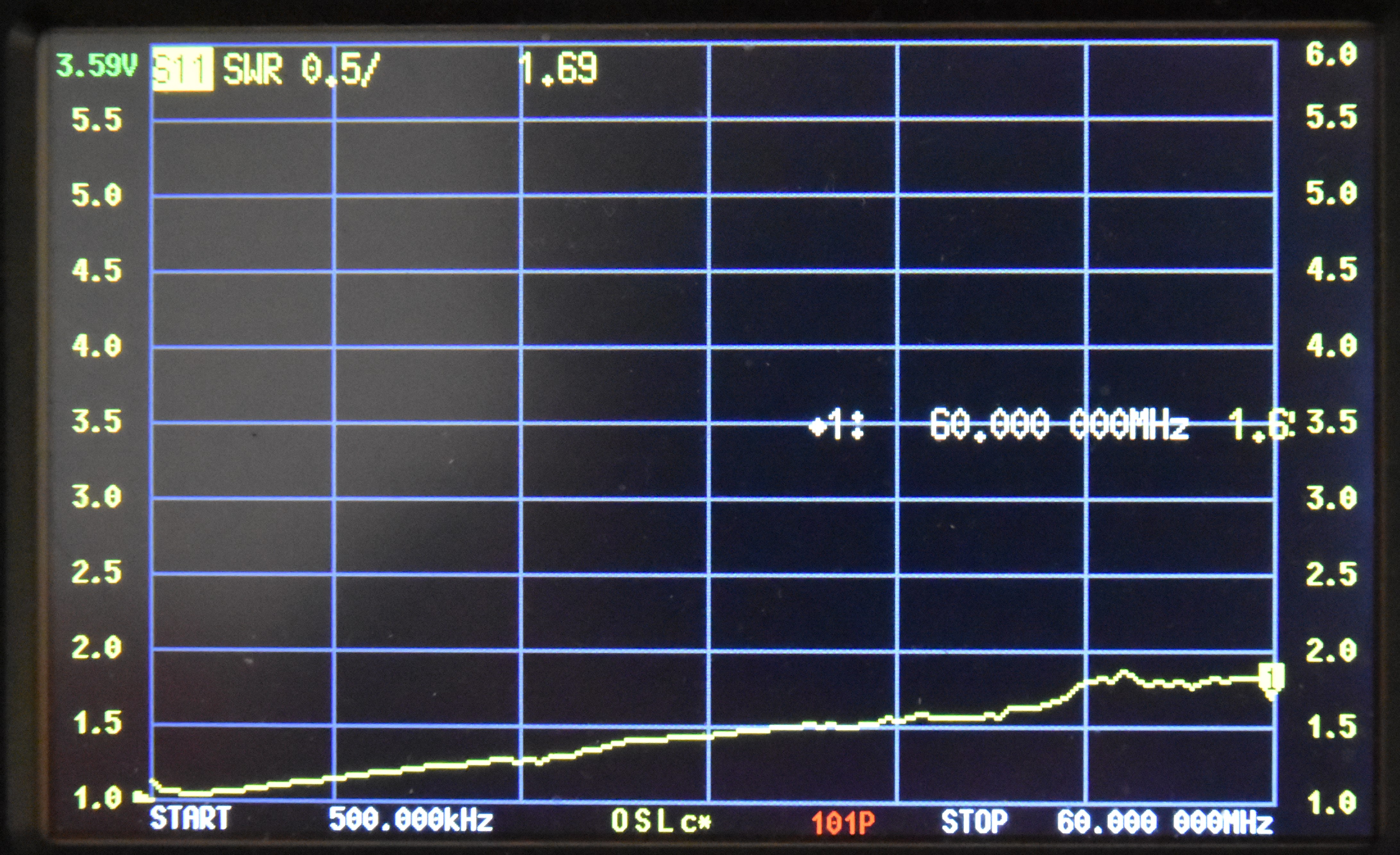
Photo
2 Shows the Nano VNA antenna analyser plot viewing a 200ohm resistive load through the
1:4 balun. Note the 200ohm resistor appears as 50ohms due to the 1:4 balun ratio
transformation resulting in an ideal SWR of 1:1. This plot shows an SWR ranging from
1.0 MHz to 60MHz with a 1.7:1 or better SWR.
For
Summary of suitable ferrite cores and core types for a frequency range of
1.0 MHz to 60MHz for power levels of 50W, 100W, and 500W continuous and SSB. It assumes good thermal management and proper balun design.
See: Power
- Ferrite Core Design
1:1
Choking Balun
The
choking balun to isolate the potential common mode RF on the coax cable
and to reduce noise pick up.

Figure
4 Schematic
of the 1:1 choking balun
|
Type
|
Choking
Balun
|
|
Ratio
|
1:1
|
|
Frequency
Range
|
3
~ 60MHz
|
|
Choking
Impedance
|
Better
than -20dB of attenuation is required.
|
|
Core
Used
|
FT140-43
Ferrite Toroid Core
|
|
Number
of turns
|
14 Turns.
(Coax - RG316/U 50 OHM)
|
|
SWR
|
1:1 Ref:
Photo 4 and 5
|
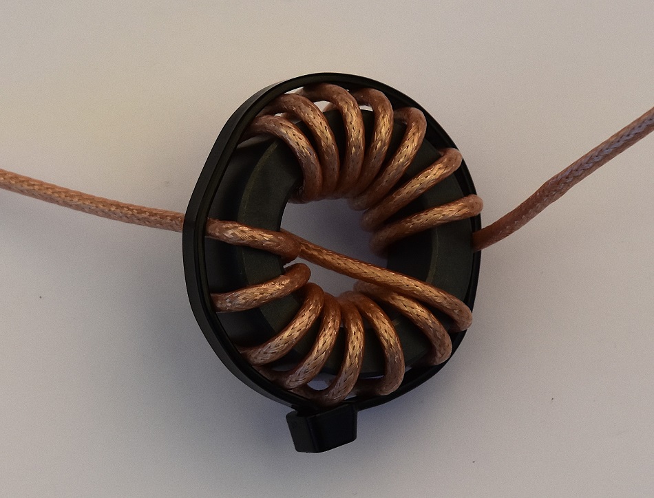
Photo
3 Choking balun assembled.
Choking
balun testing
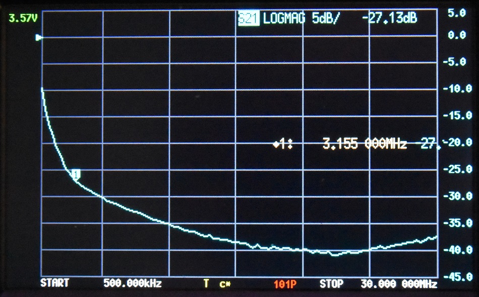
Photo
4 Shows the Nano VNA antenna analyser plot of the choking
attenuation in dB to mitigate common-mode RF current on the coax
shield. 20dB attenuation should be considered the minimum. This plot shows
a choking attenuation
of -20dB from 1.0MHz to 60MHz.
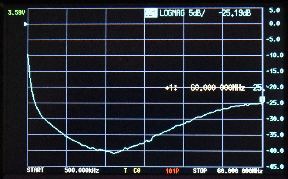
Photo
5 Shows the Nano VNA antenna analyser plot of the choking
attenuation in dB to mitigate common-mode RF current on the coax
shield. 20dB attenuation should be considered the minimum. This plot shows
a choking attenuation
of -27dB from 3.5MHz to 30MHz the broad frequency range of interest
and better than -35dB from 10MHz to 30MHz.
Mast
Head Matching Enclosure.
The
mast head matching transformers are installed in a 115 x 90 x 55mm
sealed polycarbonate enclosure.
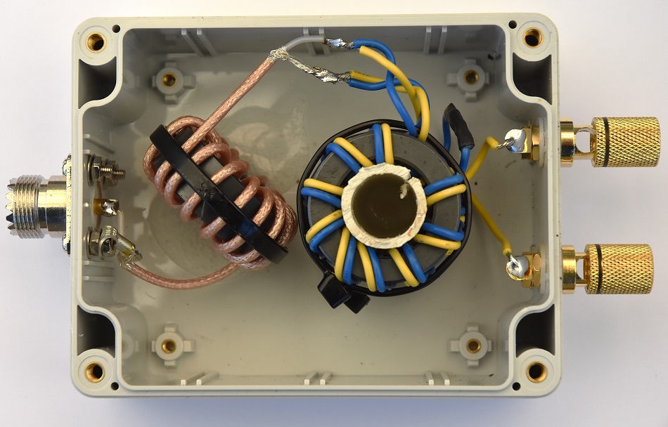
Photo
5 Mast
Head Matching Enclosure
TOP
OF PAGE
Page initiated 2 September, 2025
Page
last revised 2
September, 2025
|