|
PORTABLE
HF DOUBLET ANTENNA Portable
HF Doublet Antenna for a frequency range of 3.5MHz - 30MHz.
October 2025.
Requiring an easily
deployable and reliable antenna for portable campsite radio
communication, I selected a multi-band dipole, as I had a proven
track record of success with this type of antenna. While end-fed
wire antennas had also been used for this purpose due to their
flexibility in installation, they often produced inconsistent
performance depending on ground type and other site conditions. The
multi-band dipole will have an overall length of 30 m, which creates
some installation challenges; however, this is considered a
worthwhile trade-off. It will serve as a secondary antenna,
providing better coverage of the lower frequencies from 3.5MHz to
about 10MHz, to complement the primary smaller vertical ground-plane
antenna that covers 7MHz to 30MHz.
Various multi-band
dipole lengths were modelled using the MMANA-GAL antenna-modelling
application. The analysis concluded that a 30m overall dipole length
offered suitable performance across the HF bands. This length was
chosen because it avoids extreme impedances—in other words, it
avoids resonant lengths on all amateur HF bands. The modelling also
provided insights into likely radiation patterns and matching
requirements.
The antenna is a
balanced dipole fed at the centre, with two 15m elements on either
side. The feed point is connected to an 8m length of 450-ohm ladder
line, followed by a 4:1 balun and a 1:1 choking balun. A length of
coaxial cable then connects the system to the antenna matching unit
and SWR meter before finally reaching the transceiver.
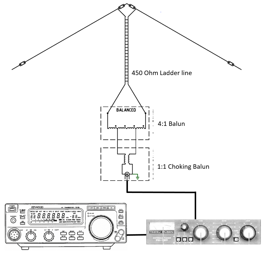
Fig
1 General
antenna, matching and radio arragment.
The below charts
indicates the likely VSWR
ratios across the HF band with a 1:1 balun
(50 Ohms), 4:1 balun (200 Ohms) and 9:1 balun (450 Ohms). The chart
clearly eliminates the opportunity to direct connection at 50 Ohms and
while 4:1 and 9:1 Balun VSWR levels are far too high for a direct
transceiver connection they are much more within the range of the
Antenna Matching Unit.
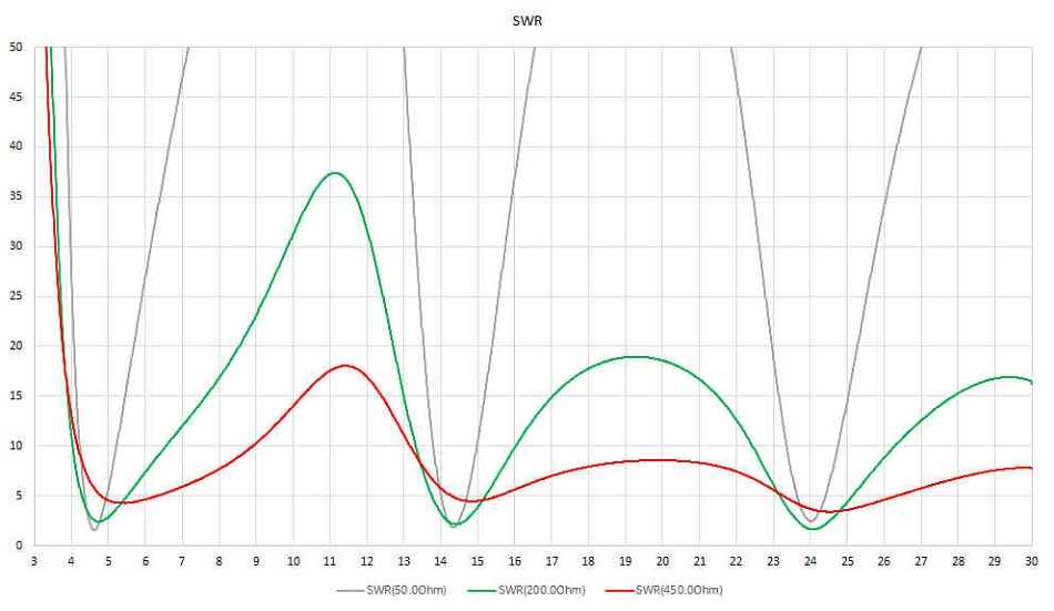
Fig
2 MMANA-GAL antenna
model prediction for VSWR ratios across the HF band for various
connection impedance.
Vertical axis is the VSWR ratio and the horizontal axis is the
frequency in MHz.
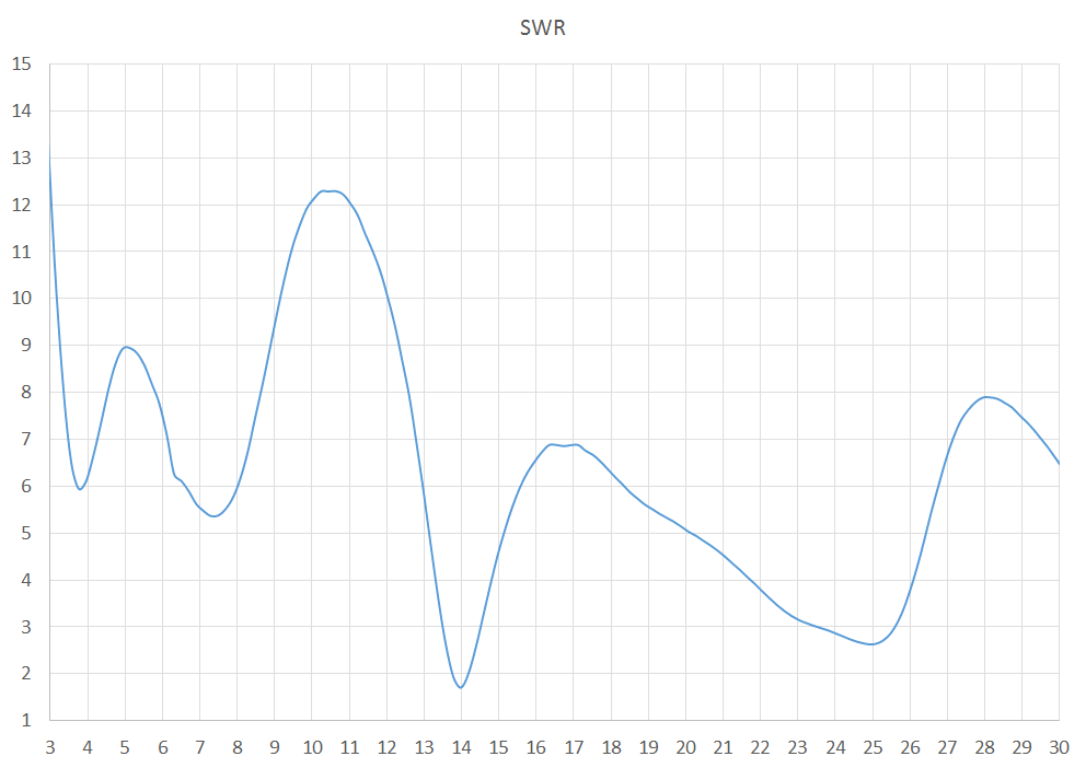
Fig
3 AIM antenna analyser
results for VSWR ratios across the HF band for connection at 4:1
Balun.
Vertical axis is the VSWR ratio and the horizontal axis is the
frequency in MHz.
Construction
The antenna is simply
two lengths of PVC cover thin gauge multi-stranded copper wire of
15mtr each (30mtr total length) attached at the centre with 6mm PVC
sheet that is designed for a rope supporting attachment at the top
and strain support attachment for the 450 ohm ladder line to the
bottom. The Ladder line is approximately 8mtr in length.
The feed-line is then
connected to a combination balun of a 4:1 impedance transformer
balun and 1:1 choking balun.
See Balun
details: HF feedline Choke & Balun-20250901
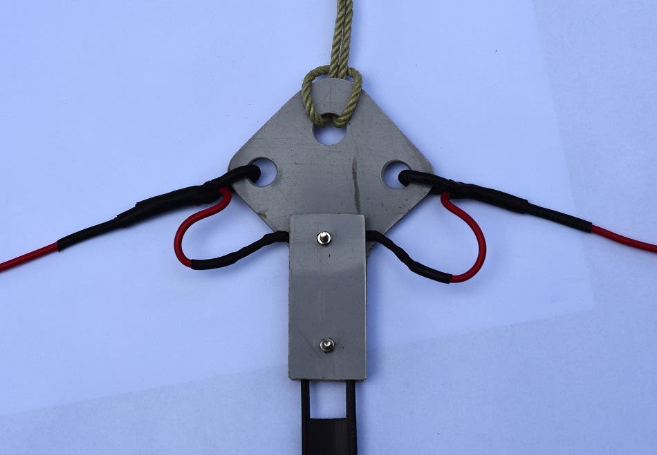
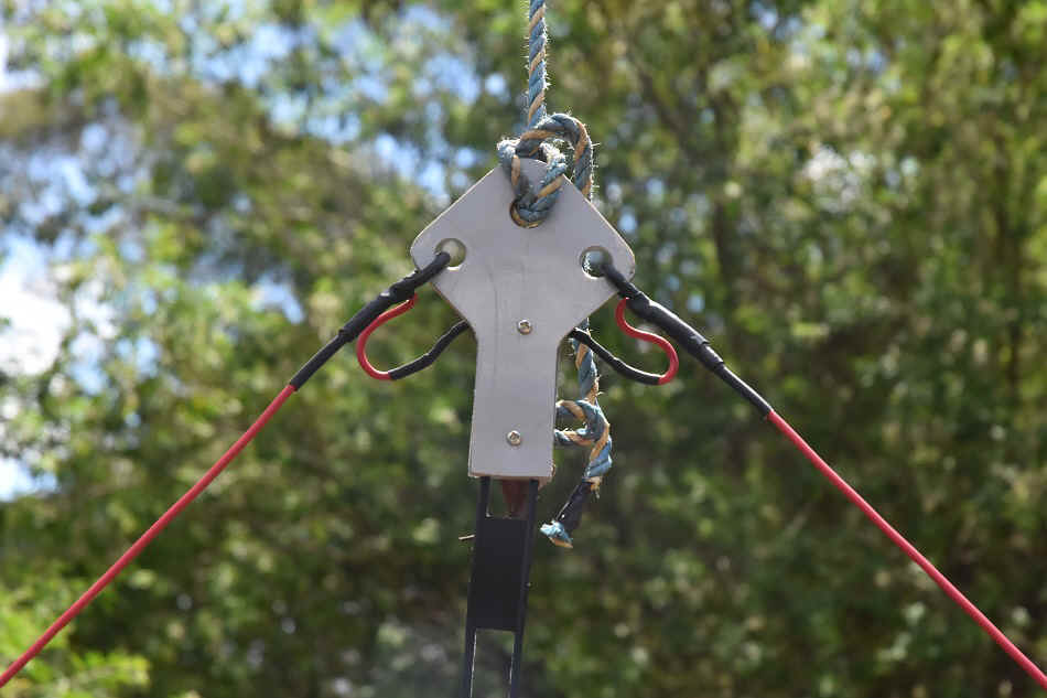
Photo
1 The dipole
centre support made from 6mm PVC sheet with large 11mm rope
attachment holes
and strain clamp attachment for the 450 ohm ladder line.
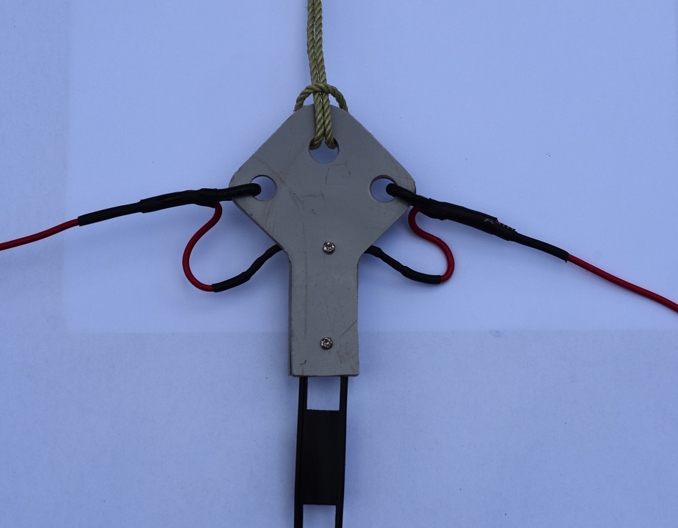
Photo
2 Front view of the dipole
centre support made from 6mm PVC sheet with large 11mm rope
attachment holes
and strain clamp attachment for the 450 ohm ladder line.
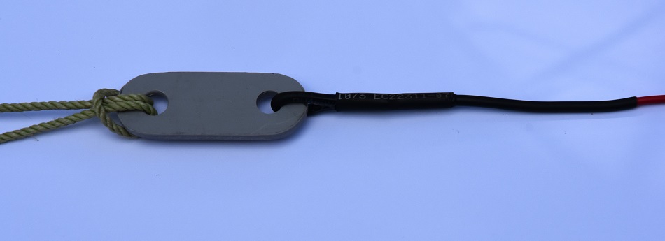
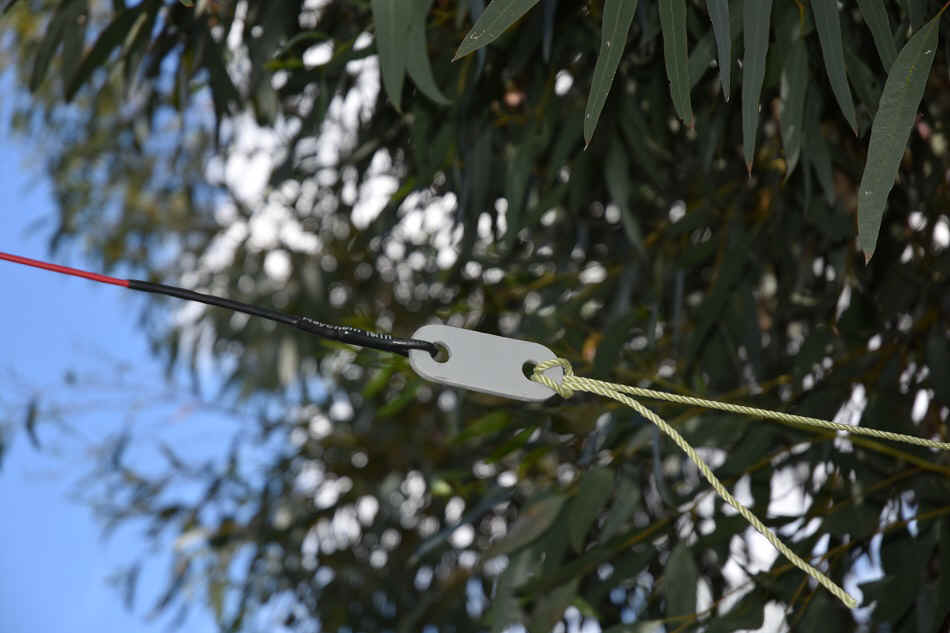
Photo
3 The dipole end
insulators are also made from 6mm PVC sheet with large 11mm rope
attachment holes.
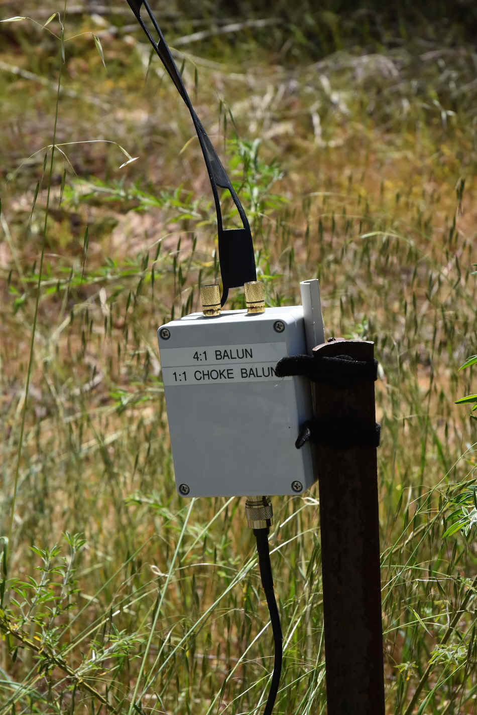
HF
ladder feed-line and other multi-band HF antennas to coaxial cable choke and 1:4 balun.
See
Balun details: HF feedline Choke & Balun-20250901
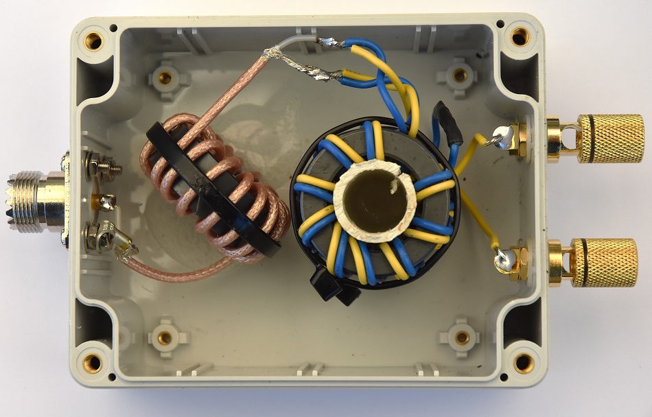
Photo
4 Antenna Balun assembly
Radiation Pattern
At an installation
height of about 8m above ground, the dipole is approximately 0.09λ
high at 80m, 0.19λ high at 40 m, and proportionally higher at
the upper bands. This height is considered low for the lower bands
and results in a high take-off angle, favouring Near Vertical
Incidence Sky-wave (NVIS) propagation on 80m and 40m, while
producing more useful DX radiation patterns on the higher bands.
Taking advantage Near
Vertical Incidence Sky-wave (NVIS) propagation for 80m and 40m
should be consistent with portable camping style operation with
longer distance contacts on this antenna and the vertical antenna
that will target bands from the 30m band above and are also consistent
with proposed needs.
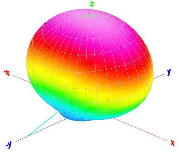
Fig 4 MMANA-GAL antenna
model prediction: At 80m a broadside
bi-directional
pattern with NVIS
enhancement due to high radiation angle for a low installation
height of 8mtr or less.
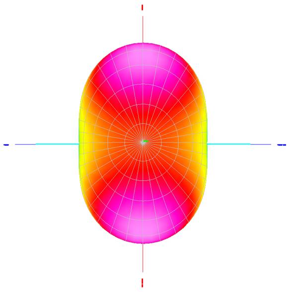
Fig 5 MMANA-GAL antenna
model prediction: At 40m the antenna develops lobes, giving more DX
potential but also nulls off the ends pf the antenna. The antenna
still has high radiation angle and is regarded as being mostly
useful for NVIS type propagation.
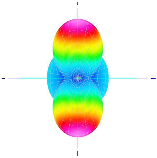
Fig 6 MMANA-GAL antenna
model prediction: At 30m the antenna develops more complex lower
radiation angle lobes favouring the broadsides of the antenna and
with nulls off the ends. The antenna is more suited for long
distance at this frequency.
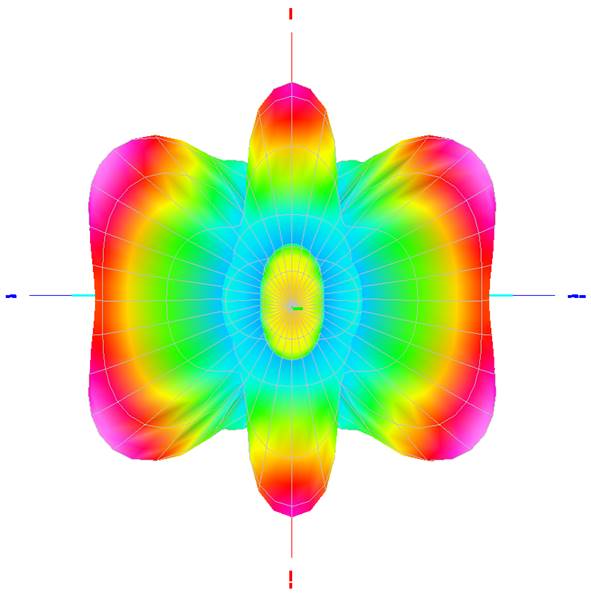
Fig 7 MMANA-GAL antenna
model prediction: At 20m and above, increasingly multi-lobed
patterns with narrower beamwidths, potentially advantageous for DX
but less predictable in coverage.
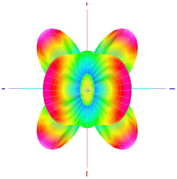
Fig 8 MMANA-GAL antenna
model prediction: The antenna at 17m a four lobed pattern and
additional higher angle lobes of the ends of the antenna.
\
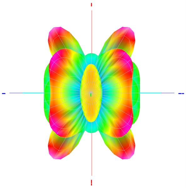
Fig 9 MMANA-GAL antenna
model prediction: The antenna at 15m with a complex four lobed
pattern.
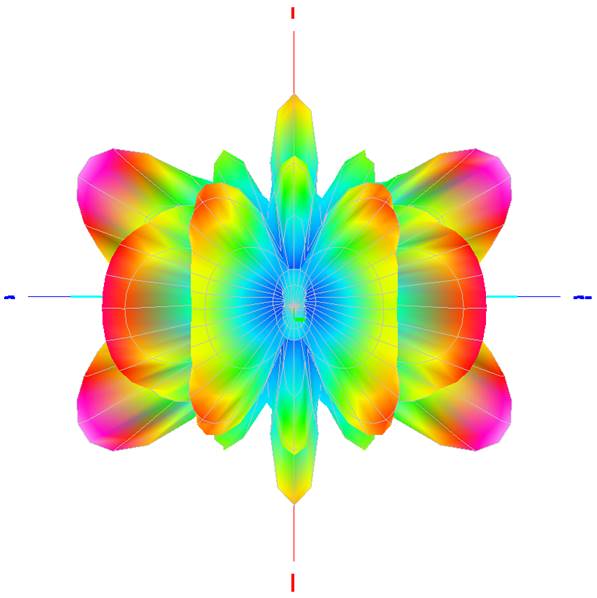
Fig 10 MMANA-GAL antenna
model prediction: The antenna at 12m a much more complex lobed
patterns.
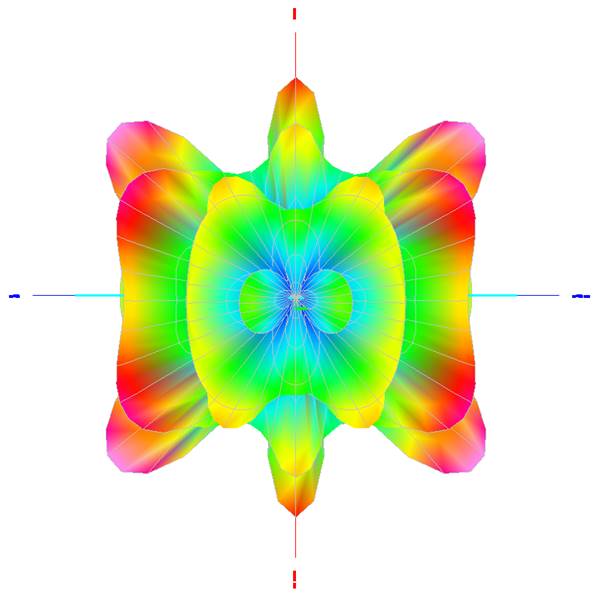
Fig 11 MMANA-GAL antenna
model prediction: The antenna at 10m with a very complex multi-lobed
pattern
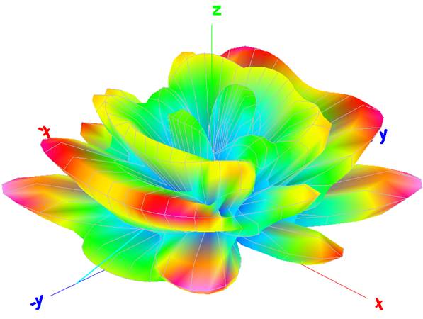
Fig
12 MMANA-GAL antenna
model prediction: A 3D view of the antenna at 10m to better display
the very complex multi-lobed radiation pattern.
At 5 to 8 m height,
performance favours local and regional contacts on the lower bands,
and medium to long-distance DX on upper HF. For the higher HF bands
the orientation of the antenna could be an important consideration.
Photo
5 The dipole
centre support.
Photo
6 The dipole end
insulators
Photo
7 Open
wire feed connection to coax cable with 4:1 Balun and choke balun.
Photo
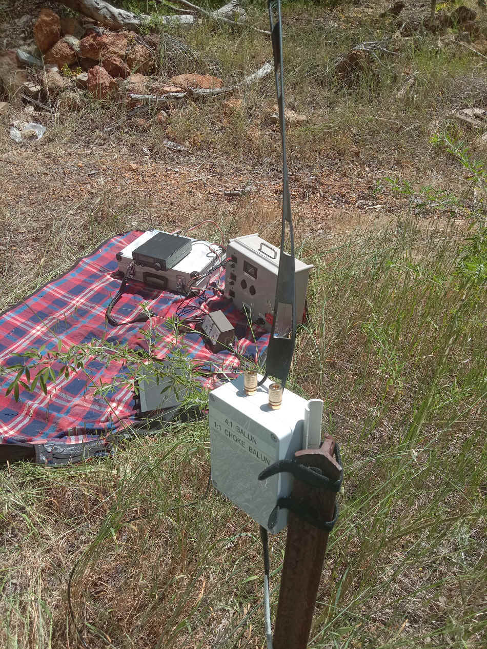
8 The
on the ground radio equipment with balun connection to the open wire transmission line in the foreground.
TOP
OF PAGE
Page initiated 25 August, 2025
Page
last revised 18
October, 2025
|