|
ACTIVE ANTENNA -
PA0RDT - Version 1
PA0RDT compact active wide-band receiving
antenna for lower frequency bands
from 10 kHz to approximately 10MHz.
The antenna is often described as an E-field
Probe Antenna as the high impedance front end amplifier measures the potential difference
between the antenna plate (E antenna) and the grounded mast or coax
screen. For a more comprehensive explanation see the Fundamentals of
the MiniWhip antenna - Pieter-Tjerk de Boer, PA3FWM at http://www.pa3fwm.nl/technotes/tn07.html
The active
antenna designed by PA0RDT may offer a practical technique for exploring radio frequencies
below 500kHz and is reported to offer good performance in the
lower frequency bands from 10kHz to at least 10MHz. Slightly modified
from the original design to take advantage of available components
this active antenna is intended to trial this type of receiving
system.
The MPF102
has similar characteristics to the J310 transistor with the advantage of the later being low
noise however with general higher noise
levels of the lower frequencies this should not be a problem.

Fig
1 The
compact active wide-band receiving
antenna unit schematic.
|
ID
|
DESCRIPTION
|
QTY
|
|
C1,
2, 3 & 5
|
CAPACITOR,
CERAMIC - 470n, 50V
|
4
|
|
L1
|
INDUCTOR,
470uH
|
1
|
|
R1,
2 & 3
|
RESISTOR
- CARBON 1M,
0.25W
|
3
|
|
R4
|
RESISTOR
- CARBON 680R, 0.25W
|
1
|
|
R5
|
RESISTOR
- CARBON 10k, 0.25W
|
1
|
|
R6
|
RESISTOR
- CARBON 3k3,
0.25W
|
1
|
|
R7
|
RESISTOR
- CARBON 47R, 0.25W
|
1
|
|
R8
|
RESISTOR
- CARBON 330R, 0.25W
|
1
|
|
Q2
|
TRANSISTOR
- 2N3904 - NPN
|
1
|
|
Q1
|
TRANSISTOR
- MPF102 - J-FET
|
1
|
Fig
2 List of components.
Construction
The
circuit is assembled on single sided PCB with the copper clad board separated
down the middle. The left side forms the antenna and the right side is
ground and has a section of Vero-board glued to the back for component
connections.
The
final board is mounted in a section of PVC water pipe for weather protection.
The board is connected via a very short section of coax to a male N
type connector that is fixed to the base of the water pipe bottom end
cap. Constructing antennas around the male N type connector allows for
mounting on the standard station Generic Antenna
Mount.
The active
antenna is powered with approximately 12 ~ 15V via the connecting coax
cable with the masthead coaxial
cable power feed unit.

Fig
3 The
compact active wide-band receiving
antenna board dimensions viewed from the back.
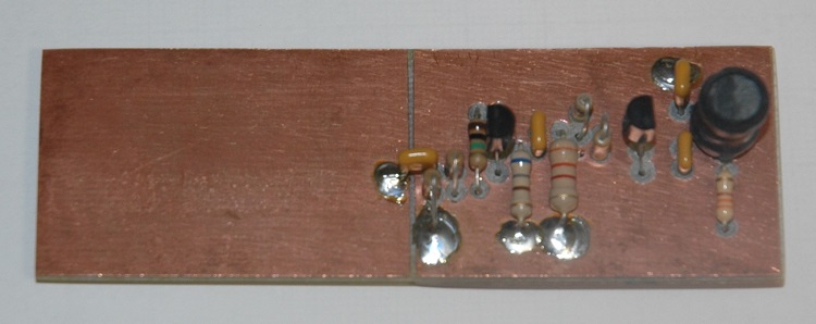
Photo 1
The
compact active wide-band receiving
antenna circuit board assembled viewed from the front.
Details
of the assembly of the board and male N type connector with the water
pipe bottom end cap is shown below including the aluminium mounting
disc for the N type connector attachment.
|

|

|
|
Photo 2
The active
antenna weather cover mounting plate with the N type connector
attached. Top view.
|
Photo 3 The active
antenna weather cover with the N type connector attached. Bottom
view.
|

Photo
4 The active antenna circuit
board attracted via sort length of coax to the N type connector within
the protective weather cover bottom cap.

Photo
5 The active antenna circuit board attracted via sort length of
coax to the N type connector within the protective weather cover
bottom cap. Bottom view.
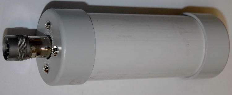
Photo
6 The
active antenna completed assembly.
Installation:
The
original mini-whip article by Roelof Bakker, PA0RDT states that the
active antenna should be installed on an insulated mast, however there
is evidence that the active antenna in fact uses the outside of the
coax shield as a ground path there by making the coax shield an
integral part of the antenna. With the coax cable entering the radio
room it is highly likely that the system will pick up all sorts of
noise from equipment such as computers etcetera; therefore in this installation
it is intended that the mast will be conductive and electrically
connected to ground to encourage a cleaner system. Despite attempts at choking the coax cable with a
balun, it yelled no detectable improvement as the antenna is of a
very high impedance including the way that the coax shield acts as
part of the antenna and there appears no way to isolate the coax shield
from being part of the antenna by way of choking.

Fig
4 Active antenna installation details
Key
installation hardware other than the active antenna are shown below
with links to detail pages.
|

|

|
|
Photo 7 The active
antenna installed on stubby mast with out the R.F. choke
at this stage.
|
Photo 8 The active
antenna installed generic antenna mount details.
|
|

|
|
Photo 9 The
masthead coaxial
cable power feed unit install in the shack with the computer soundcard
interface unit and the TS930 transceiver.
|
Performance:
First
Trial 18/02/2016
While
this is a bit of a rough comparison it is very encouraging.
Comparison
set up:
Antenna#1:
10m Band Sloper connected directly to the
radio with no ATU.
PA0RDT
Active Antenna: Was located at the top of an iconic Australian metal cloths line.
Radio:
TS930S. The broadcast band (500 ~ 1600kHz) on this radio is deliberately
less sensitive at 32uV
Active Antenna in this comparison has demonstrated consistently very
good results when compared to the Antenna#1 results. While this
appears to be good a results for the active antenna the setup of both
antennas is less than optimal, however it is encouraging.
|
STN
ID
|
Frequency
kHz
|
Antenna#1
Signal
|
PA0RDT
Active Antenna Signal
|
Comments
|
|
CLK
|
200
|
S+20
|
S+40
|
NDB
Less than 50Watts
|
|
JT
|
281
|
Nil. noise floor S+10
|
S+10 Above noise
floor.
|
NDB
50Watts
|
|
PEA
|
340
|
S+10
|
S+45
|
NDB
2kW
|
|
PH
|
372
|
S9
|
S+45
|
NDB
|
|
6DL
|
531
|
S1
|
S7
|
BC station, Dalwallinu
WA
|
|
6WA
|
558
|
S2
|
S7
|
BC station, Wagin WA
|
|
6NM
|
1214
|
S+35
|
S+40
|
Local BC, Northam 5km
away.
|
Specifications:
Frequency
rage:
10kHz to 10MHz
Power
Consumption: 18mA at 12V
Output
impedance: 50
ohms approximately
References:
For
powering the
compact active wide-band receiving
antenna via the coax cable. See Masthead coax power feed
unit.
Details
of the generic antenna mount. See: Generic Antenna
Mount.
WSPR 160m
band activity data recorded for a 4 x 24 hour periods 01-04/05/2017:
WSPR_160m 20170504A
Compare the
compact active antenna with the main station antenna
Reference
articles:
Roelof
Bakker, PA0RDT mini-whip article. See: http://dl1dbc.net/SAQ/Mwhip/pa0rdt-Mini-Whip.pdf
Roelof
Bakker, PA0RDT mini-whip article 2006. See: http://www.arimodena.it/tecnica/progetti/mini-whip/doc/article-pa0rdt-mini-whip.pdf
Fundamentals
of the MiniWhip antenna - Pieter-Tjerk
de Boer, PA3FWM. See: http://www.pa3fwm.nl/technotes/tn07.html
Grounding
of MiniWhip and other active whip antennas - Pieter-Tjerk
de Boer, PA3FWM. See: http://www.pa3fwm.nl/technotes/tn09d.html
TOP
OF PAGE
Page
last revised 20 April, 2017
Page
last revised 12 March 2022
|