|
10M BAND SLOPER
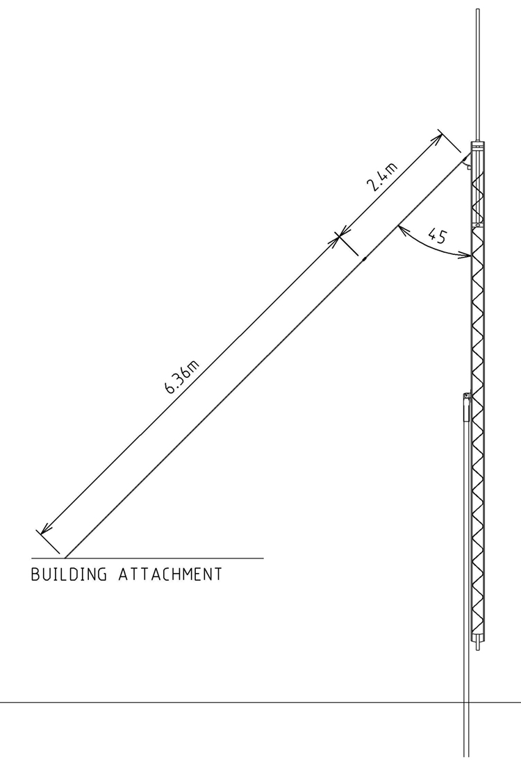
Guy wire sloper antenna suitable for 10m band. Install September 2012.
Always
attempting to get the most from any antenna and tower system I decided
that there was no good reason that the tower guy wires could not be
used as additional antenna radiators. Although the guy wires are
galvanized steel, not the first choice for an antenna due to its
higher material resistance, they are however a relatively heavier gauge
compared to what had been used for the multiband dipole, hopefully
negating the poorer conductivity of the steel. The 10m band sloper
antenna is based on the experience of the 40/15m band guy wire sloper
that is attach to the same tower.

Sloper
antenna for the 10m bands cut into tower's south guy wire.
According to the ARRL Antenna Book 18th Addition there are two
sloper design definitions a sloping λ/2 dipole is known among
radio amateurs as a 'full sloper' or just 'sloper.' If only one half
of it is used it becomes a 'half sloper.' The performance of the two
types of sloping antennas are similar: They exhibit some directivity
in the direction of the slope and radiate energy at low angles
respective to the horizon. The wave polarization is vertical. The
amount of directivity will range from 3 to 6 dB, depending upon the
individual installation, and will be observed in the slope direction.
The so called sloper antennas all have one thing in common they are
problematic when it comes to matching. There are three components that
interact to produce the feed point impedance value and therefore the
SWR result. First the length of the radiator element or wire from the
tower, secondly the angle that the radiating element has with the
tower and finally the tower and other attached hardware it's self.
The final SWR is adjusted by altering the length of the radiating wire
and the attachment angle. The tower with its antennas and other
hardware offers less of an opportunity for adjustment with exception
of an improved earth and counterpoise system.
In this case by using an existing guy wire there is in fact only the
radiating element length available for adjustment with the position of
the guy wire being dictated by other real world considerations. The
examples of the sloper antenna that is presented in the ARRL Antenna
Book 18th Addition and other articles show the radiating
wire angle as being 45deg.
Having conceded that the SWR may not be ideal the aim was simple to get
to as lower value as was possible given the installation constraints
and use an ATU to correct any less than ideal SWR figure in so far as
the transceiver was concerned. At 28MHz the 21mtr run of RG213 should
not introduce too much loss into the system. For example if a SWR
value of 3:1 at 28.40MHz was achieved the additional coax line loses
would be 0.326dB. See Fig #1 and Graph #1
|
SWR
|
24.95
MHz
@ 100W
|
28.50MHz
@ 100W
|
|
Coax
Line lose
|
Power
at the antenna
|
Coax
Line lose
|
Power
at the antenna
|
|
1.0
- 1
|
0.536dB
|
88.382W
|
0.578dB
|
87.541W
|
|
1.5
- 1
|
0.576dB
|
87.583W
|
0.620dB
|
86.697W
|
|
2.0
- 1
|
0.654dB
|
86.029W
|
0.703dB
|
85.057W
|
|
2.5
- 1
|
0.745dB
|
84.234W
|
0.800dB
|
83.169W
|
|
3.0
- 1
|
0.842dB
|
82.373W
|
0.904dB
|
81.216W
|
|
4.0
- 1
|
1.041dB
|
78.694W
|
1.114dB
|
77.372W
|
|
5.0
- 1
|
1.237dB
|
75.213W
|
1.322dB
|
73.755W
|
|
6.0
- 1
|
1.428dB
|
71.974W
|
1.524dB
|
70.406W
|
|
8.0
- 1
|
1.255dB
|
66.198W
|
1.906dB
|
64.474W
|
|
10.0
- 1
|
2.13dB
|
61.241W
|
2.26dB
|
59.425W
|
|
|
Fig
#1 Comparative coax line loses for a 21 meter run of RG213 coax for
24.95 MHz and 28.50 MHz at various SWR values |
|

|
|
Graph
#1 Comparative system output power for a 21 meter run of RG213 coax
for 24.95 MHz and 28.50 MHz at various SWR values for a transmitter input
power of 100W
|
Construction
Construction is very simple; the existing galvanized steel
guy wire has two insulators cut into it, one at the top as near to
the tower as is possible and the other towards the ground attachment
end. The length of wire between the two insulators is about λ/4
at 28.5MHz plus a bit. The insulator cut in at the ground attachment
end has wire fed through the insulator with a longish tails of about 1
meter for easy adjustment of the final radiator length. After
measurement and adjustment the guy wire can be more neatly terminated
to the insulator.
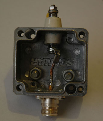
The coax cable is terminated in a weatherproof aluminium box that should
be resilient to the most hostile environments requiring little if any
maintenance for the life of the antenna.
|

|

|
|
Photo
1. Internal view of the Weatherproof coax termination box.
|
Photo
2.
Weatherproof coax termination box.
The spacer block at the rear is to place the antenna connection
away from the tower.
|
|

|
|
Photo
3. Tower end assembly during installation with the
tower in the tilted over position.
|
Antenna
testing and modelling.
All result shown are the Sloper antenna viewed with the AIM 4170C antenna analyser as see at the
transceiver end of the coax.
AIM 4170C antenna analyser explanation;
|
SWR
|
Standing Wave Ratio.
|
|
Zmag
|
Total Impedance.
|
|
Rs
|
Resistive component of the total impedance
|
|
Xs
|
Reactive component of the total impedance also indicating the +/-sign
of the value. Inductive being a positive value and capacitive
being a negative number.
|
|
Theta
|
Phase angle between voltage and current.
|
|
Return Loss
|
Total reflected system loss.
|

Graph
#2 AIM 4170C antenna analyser display of the HF spectrum from 20 -
30MHz as would be seen by the
transceiver.

Graph
#3 AIM 4170C antenna analyser display of the HF spectrum from 28 - 29.8 MHz
indicates that while not suitable for directly connecting to a
transceiver, with an inline ATU a usable antenna with minimal line loss
is available over the 10m band.

Graph
#4 AIM 4170C antenna analyser display of the HF spectrum from 24.80 - 25.00 MHz
indicates that the antenna could be directly connecting to a
transceiver, however it is intended that ATU will be used for
operations on the 12m band.

Graph
#5 AIM 4170C antenna analyser display of the HF spectrum from 21.00 - 21.50 MHz
indicates that while not suitable for directly connecting to a
transceiver, with an inline ATU a usable antenna with minimal line loss
is available over the 15m band.
Operational
Performance
Anecdotally
the antenna seems to be performing as predicted, that is signals often
have marked improvement over
the multi-band dipole in some
directions. The multi-band dipole experiences deep nulls in it's radiation pattern
particularly on both 12 and 10m bands and as it is an easy process to switch
between the two antennas it is simply which antenna offers the best
signal.

Figure 2 A three dimensional
view of the radiation
pattern of the 10m sloper at 28.5MHz. Radiation
plot was produced by MMANA-GAL Antenna Analyser
software.

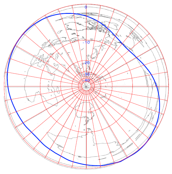
Figure 3 Radiation
pattern of the 10m sloper at 28.5MHz. The pattern has been orientated
over the great circle map centred on Northam, Western Australia.

Figure 4 Radiation
pattern of the 10m sloper at 24.90MHz. The pattern has been orientated
over the great circle map centred on Northam, Western Australia.
References
ARRL
Antenna Book 18th Addition
Coax Cable and Line Loss
Calculator http://www.arrg.us/pages/Loss-Calc.htm
Loss
in antenna conductor materials
This
article explores the potential losses of popular conductor materials.
http://www.vk1od.net/antenna/conductors/loss.htm
SWR(Standing Wave Ratio) Wikipedia http://en.wikipedia.org/wiki/Standing_wave_ratio
The
above radiation plots were produced using MMANA-GAL Antenna Analyser
software by JE3HHT, Makoto (Mako) Mori at http://hamsoft.ca/
TOP
OF PAGE
Page
last revised 12 March 2022
|