|
146MHz
1/4λ GROUND PLANE ANTENNA
146MHz
1/4λ ground plane tower mounted antenna.
Requiring a replacement antenna for my aging 2mtr band 5λ/8 wave ground plane that is primarily used for local FM simplex and repeater communication, I settled on the simpler 1λ/4 wave ground plane antenna designed for approximately 146.5MHz. The 1λ/4 wave ground plane antenna has the advantage of being a simple antenna with predictable performance. There are many comparative evaluations suggesting that there is often little difference in performance
with the 5λ/8 wave ground plane antenna when compared with the 1λ/4 wave ground plane as a
tower mounted antenna.
The internet revealed many similar designs for 1λ/4 wave ground plane antenna with one disconcerting feature; they had significant variations in dimensions including formulas that produced varying results. With the inconsistency in basic dimensions I wondered if the commonly specified 45º radial angle was in fact the ideal angle for best performance. The project was now taken back to basic principles and calculations were made based largely on information and analysis provided by the
RSGB's. VHF UHF Manual - fourth edition by G. R. Jessop, G6JP.
The 1/4 wave ground plane or monopole antenna in this instance will be mounted on a mast and therefore a perfect ground pane will not be present. The ground pane will be simulated as is normally the case with a number of metallic elements extending out horizontally from the base of the monopole element and connected to the shield of the coax. The ground plane elements number at least three, but preferable more and in this design there will be six. The length of the ground plane elements are approximately 5 -10% longer than the radiating element, but can be longer. The RSGB VHF UHF Manual by G. R.
Jessop, G6JP suggests element lengths of 0.28λ to 0.30λ

Figure 1
Complete 146MHz
1/4λ ground
plane assembly
As the name suggests the 1/4 wave ground plane has elements that are
a 1/4 of a wave length of the operating frequency in length, this however is the electrical length not the physical length. The physical length is reduced due to the effects of the diameter of the elements; the reduction is referred to as the ‘K’ factor which is typically a figure of about 0.92 to 0.98, this figure is then multiplied by the electrical wave length to give the resultant physical length.
The below calculation determines the physical length of the radiating element ‘A’ and the six radial elements ‘B’.
The 'B' elements are as discussed earlier to be about 10% longer,
therefore the formula for the 'B' elements has a 1.1 multiplier.


Frequency = Frequency in MHz,
el = The length of the antenna element. A 1/4 wave element will be presented as 0.25 for example.
K = K factor referred to in the below
calculation and chart.
The
result value for the above calculations would be in metre, but has
been presented in mm as more convenient value in the practical
approach to this calculation the result in metres would be multiplied
by 1000 to present millimetres.
The elements are all electrical quarter wavelengths not physical lengths, with the physical length being slightly shorter. The basic wavelength calculation is multiplied by a factor of ‘K’. Typically K is a value between 0.92 and 098 and is mainly dependant on the ratio of the wavelength and the diameter of the wire or rod used. The K factor can be derived from the below
Figure 2 Chart and the below simple formula. In this case the
6mm element rod at frequency of 146MHz results in a ration of 167 which is referred
up from the bottom of the 'K' factor chart to the curve and then referred
across to the multiplying factor which in this case was determined as approximately
0.945.

HWCD_Ratio = Half Wavelength to Conductor Diameter Ration.
Half_Wavelength = The half wavelength of the 2m band being
obviously about 1000mm.
Cond_Dia = The diameter of the rod or conductor used in the
antenna in mm. In this case 6mm

Figure 2
'K' Factor chart that determines the element multiplier factor based on the ratio of the diameter of the conductor diameter to a half wave length.
A spreadsheet with element length formula has been presented in the below table indicating the ideal lengths for the radiating and radial elements for various local Australian and some international amateur radio bands.
All spreadsheet calculations have assumed a 'K' factor of 0.945 which
is likely to be different given the different wavelengths and rod diameter
that may be employed for a practical antenna.
|
Frequency
(MHz)
|
A
(Radiating Element)
|
B
(Radial Elements) mm
|
|
mm
|
inches
|
mm
|
inches
|
|
52,50
|
1350
|
53.1
|
1485
|
58.5
|
|
70,25
|
1009
|
39.7
|
1110
|
43.7
|
|
146,50
|
484
|
19.0
|
532
|
21.0
|
|
222,00
|
319
|
12.6
|
351
|
13.8
|
|
435,00
|
163
|
6.4
|
179
|
7.1
|
Figure 3 Table of
1/4λ Ground Plan element dimensions for various local Australian and some international amateur radio bands.
With 4NEC2 an NEC based antenna modelling and optimizing computer application the proposed
1/4λ wave ground plane antenna was model tested for various element dimensions and radial element angles. The 4NEC2 optimizer feature was run with obvious goals such as maximum gain to the horizon at a minimum
SWR. While the model broadly agreed with above table it did indicate that the ideal radial down angle should be approximately 40º and that the radiating element ‘A’ should be
notable shorter than the length shown in the above table, 472mm as compared to
484mm respectively.
The conclusion is that the design will be based on the table figures with the radial down angle being 40º, in fact the radiating element will be prudently slightly longer
than that presenting the table and experimentally pruned for best results.
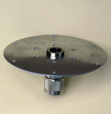
Construction
The antenna is constructed around a standard male N connector with a 100mm diameter aluminium radial mounting disk with a 15mm centre hole
to attach to the N connector with the standard coax gland screw cap as shown in
Figure 3 and Photos 1 and 2. The radial elements have been attached with 2mm diameter pop-rivets to the mounting disk and angled down at 40 deg approximately 25mm out from the disc edge. Bending the elements too close to the pop-rivets holes may cause the
aluminium tube to break at the section weaken by the hole.
The radiating element is fitted to a standard male N connector's coax centre pin and positioned in the N connector and secured with two part epoxy. A small rubber grommet has been fashioned to fit tightly in the end of the N connector body with a smearing of
marine grade silicon to make to assembly water proof.
The antenna mounting is a standard antenna mirror mount bracket with a female to female N connector bulkhead socket fitted
for all antennas are to be constructed around male N connectors. This arrangement should be suitable for simple antennas such as 1/4 wave ground plane from frequencies as low as 50MHz to more complex collinear antennas in low GHz bands and represents a convenient test bed for trialling various antenna development. See:
Generic Antenna Mount.

Figure
3
146MHz
1/4λ ground plane
radial element mounting
plate.
|

|
|
|
Photo
1 Ground plane
radial element mounting plate with related components.
|
Photo
2 Ground plane
radial element mounting plate assembly
|
|

|

|
|
Photo 3 'N'
Type connector pin attached to the radiator element with a short
length of copper wire soldered to a tinned copper sleeve and
them crimped into the aluminium tube.
|
Photo 4
Radiator brass screw adjustment. Brass screw has aluminium
grease applied and after final adjustment is crimped into the
aluminium tube and sealed with marine grade silicon.
|

Figure
4
146MHz
1/4λ ground plane
radial element assembled.
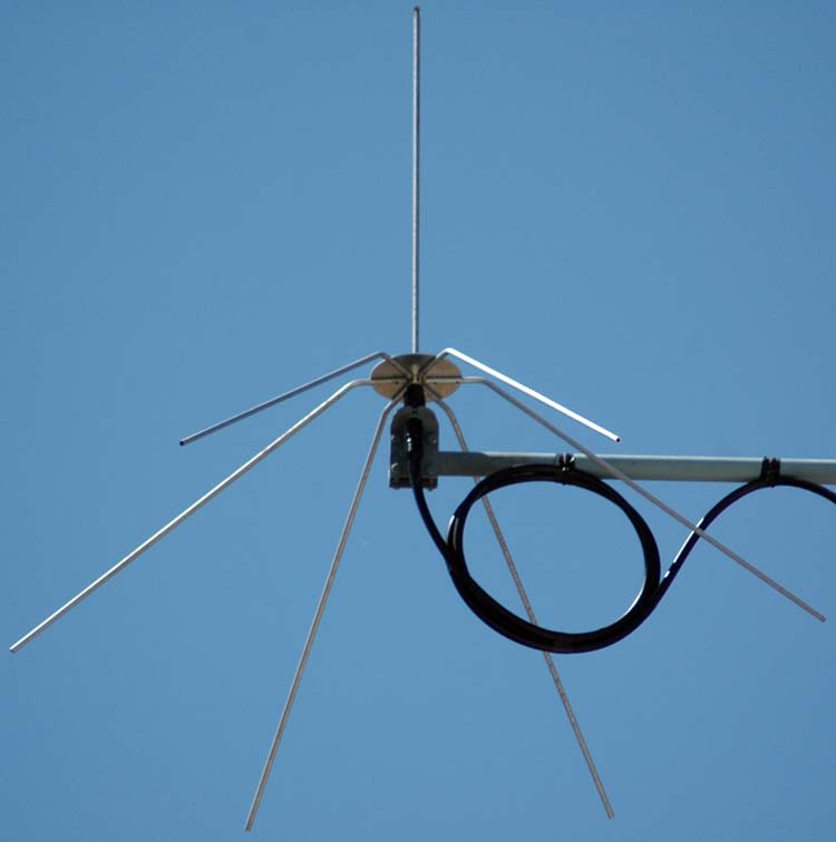
Photo
5 146MHz
1/4λ ground plane
assembled and installed.
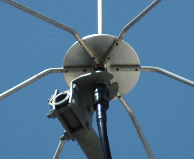
Photo
6 146MHz
1/4λ ground plane
installed and showing mounting details.

Figure
5 Radiation
plot for 146.5MHz were produced using NEC based antenna modeller and optimizer
4NEC2.
Antenna
testing
With the antenna assembled on an easily
accessible test mast well clear of the ground and surrounding metallic
objects, the antenna was connected to an AIM 4170C antenna analyser to
ascertain how the antenna loaded up.
The goal here is to find the lowest SWR
for the operating
frequency of 146.5MHz and ideally have the resonant frequency as close
as is possible to the same frequency
The AIM 4170C produces a display of all
relevant data and most importantly it can project it's analysis to
the antenna end of the coax giving a truer picture of the antenna.
With only the most modest adjustment of
the radiator adjustment screw an SWR of 1.03 was
realised at 146.30MHz with a resonant frequency at 146.607MHz.
The SWR was low across the full 2m band with only maximum of 1.2 at
148MHz. The phase angle shown in purple displays a shallow zero angle
crossing at 146.6074MHz indicating the resonant frequency of the
antenna.
The best results were achieved with a
final radiating element longer by about 10mm from 4NEC2
modelling reinforcing the conservative approach of leaving a little
extra length for experimental pruning.
AIM 4170C antenna analyser explanation;
|
SWR
|
Standing Wave Ratio.
|
|
Zmag
|
Total Impedance.
|
|
Phase
|
Phase angle between voltage and current.
|

The final on air test was
what the S meter reading would be for the VK6REC repeater that had
usually presented an S3 signal for the 146MHz
5/8 ground plane
antenna. The new 1/4 wave ground plane antenna received the
VK6REC repeater also at S3. This was not entirely surprising as the
there had been some antenna modelling done by others that suggested
that the 5/8 ground plane offered little if any advantage over the simpler 1/4 wave ground plane as a tower
mounted antenna as I was utilising them.
Details
of the generic antenna mount. See: Generic Antenna
Mount.
TOP
OF PAGE
Page
last revised 12 March 2022
|