|
146MHz 5/8 GROUND PLANE ANTENNA
146MHz
5/8 ground plane tower mounted antenna. Install December 2010
Requiring a new 2 metre band antenna for
local FM simplex and repeater communication and after evaluated a
couple of the main contenders for the project I settled on the 5λ/8
wave ground plane to be designed for approximately 146.5MHz.
The reason for selecting the 5λ/8
wave ground plane is that for a simple single element antenna it
appeared to have increased capture aperture when compared to the
standard λ/4 wave length ground plane antenna and has a relatively
low angles of radiation in comparison with other similar antennas.
The decision to proceed with the 5/8
wave ground plane antenna was largely based information and analysis
provided by the RSGB's. VHF UHF Manual - fourth edition by G. R.
Jessop, G6JP
Theory
The increased capture aperture or gain
for single radiating element increases as the radiating element length
is increased until the length of the radiator exceeds the magical 5λ8
wave length at which point the increasing radiator length causes the
radiation pattern to begin breaking up into a number lobes and nulls.
The optimum length is in fact equal to or slightly less than 0.6λ.
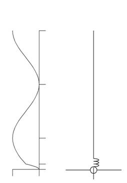
The standard quarter-wave radiator
loads up against a ground plan with a typical impedance of 36Ω
which will match the standard 50Ω coax feed line with a SWR
(standing wave ration) of about 1.5 to 1. Figure 1 show the impedance
distribution along the radiating element of a typical λ/4 ground
plan antenna with the ideal low impedance at the feed point. When the radiating
element is extended out to a half-wave length we are now looking at a
high impedance node at the feed point as shown in figure 2 that is
impossible to match with the 50Ω coax feed line without some sort of
matching circuit. If however the radiator element is increased to a
3/4 wave length the feed line will see an impedance value at the feed
point that is similar to that of the quarter-wave radiator as shown in
figure 3, however while this overcomes the matching issue the 3/4 wave
length introduces a poorer radiation pattern.
The trick is to make the 5λ/8
radiator appear to the feed line as if it were a 3/4 wave length;
establishing a good impedance match while at the same time achieving
the ideal low angle of radiation that can be realised through the 5/8
wave radiator. By add a series loading coil at the base of the
radiator to compensating for the lost λ/8 section a match of close
to 50Ω can be obtained as shown in figure 4. It is also much easy
to design a matching circuit for a 5λ/8 radiator than the more
extreme impedance presented by the 1λ/2 radiator.
|
 |

|
| Figure
1 λ/4 Radiator
Impedance
|
Figure
2 λ/2 Radiator
Impedance |
|
 |
|
| Figure
3 3λ/4 Radiator
Impedance
|
Figure 4
5λ/8 Radiator Impedance
|
Design
Having reviewed a number of designs I
decided that the simplest approach was to cut a sample radiator to the
physical 5λ8 for 146.5MHz reducing the overall length by about 5% to
allow for the material physical diameter and then forming a loading
coil from a λ/8 equivalent length of enamelled coated copper
wire. The size of the
loading coil is then adjusted until a sufficiently good match is
achieved.
The design consists of a re-hashed
commercial whip antenna that was design for an unknown frequency,
possibly low band VHF. The original antenna consisted of a stainless
steel whip mounted on an insulated tube containing some sort of
loading coil. After cutting thought the bottom end of the tube too asses the
construction the existing loading coil was removed.
At this point it was decided to wind
the new loading coil over the outside of the insulated tube and
soldered the coil tails to the tube end caps, allowing for easy
removal and experimental adjustment of the coil. The length of the
loading coil wire was determined by the physical length of λ/8 at
146.5MHz less 5% to allow for the effect of the wire diameter and less
the length of any metal antenna hardware between the bottom end of the
coil and the attachment with feed line.
The additional tail from the top of the coil would ultimately
be deducted of the final length of the 5λ/8 radiator as it would
be part of the radiator.
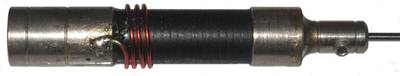
Photo 1
Installed re-designed matching coil using recovered insulated
tube.
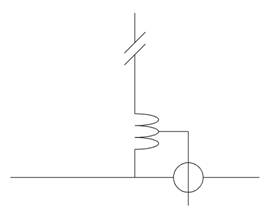
There are two loading coil
configuration for the 5λ/8 radiator. The first being popular with
commercial mobile manufactures and which is also the approach that I
have taken, which is to simply add the loading coil in series with
base of the radiator. See fig 5. The second slightly more complicated
method to set up is to ground the base of radiating element to the
ground plan via the coil and tap the feed line into a the coil as in
fig 6. The second method is in many way superior in that it allows the
antenna to be turned to resonance eliminating any reactive component
while achieving a perfect match to the 50Ω coax feed line. The
first method is a bit of a compromise in that to achieve a good match
to the feed line; however the antenna may be some what reactive.
The second method has the benefit that when
the antenna is mound high on a mast that the entire antenna is at DC
ground and will give some lightning protection to attached equipment. While the
second method requires a lot more trial and error, it represents the
superior approach and is intended to be employed on future prototype
antennas of this type.
|
 |
|
| Figure
5 Series matching coil
|
Figure
6 Grounded matching coil
|
Despite the antenna and mounting
hardware being of a reworked mobile vertical antenna, the intention is
that it be used as mast mounted antenna and therefore feed it with
something better than RG58. A
solution was to redesign a standards mobile antenna mount with a
Female 'N' type coax cable connector that would be robust and more
importantly weather proof.

Photo
3
Standard mobile antenna mount
adapted to the ground plane assembly - Top view
Below is an explanation
of how the standard mobile antenna mount was modified to for the
feed attachment for the ground plane antenna. It is important to
remember that mobile antenna mount of this type vary considerably
in the design and any attempt to duplicate the this process
should use this description as a guide only.

Figure 7 Explanation of how the standard mobile antenna mount was modified
for the feed attachment for the ground plane antenna.
A - Retaining nut.
B - Weather proof
cone.
C - Aerial mounting
stud and insert guide.
D - Coax screen
ground insert. (Remove, not required)
E - Ground plane
mounting base.
F - Standard N
connector (Female)
The standard mobile antenna mount
is disassembled with the coax screen
ground insert being discarded and the insert guide skirt of
the aerial mounting stud assembly trimmed so that it
remains flush with the bottom of the weather proof cone when
assembled. The female N connector is pop-riveted to the
ground plan base disc and the aerial mounting stud is
connected with a very short and flexible lead to the female N
connector centre pin. The weather proof cone is then
seated over the aerial mounting stud and fixed in place
with two self tapper screw to the ground plan base disc from beneath.
A light bead of marine grade silicon is applied to the bottom of
the weather proof cone before it is attached. The
retaining nut is then installed with care not to over tighten.
See below complete assembly.
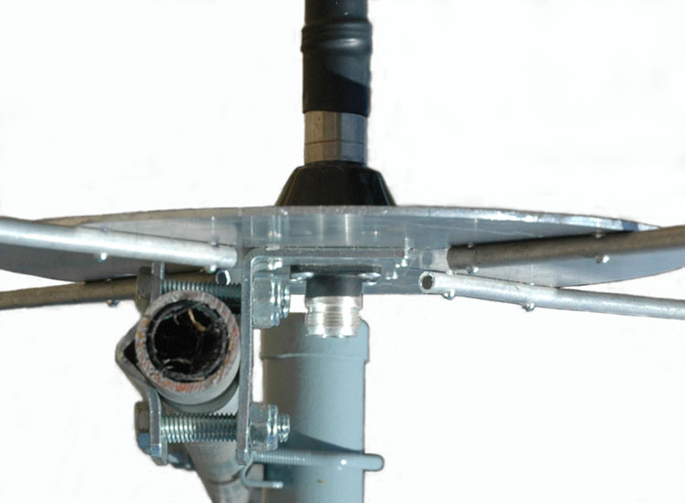
Photo 4
Standard mobile antenna mount
adapted to the ground plane assembly - Side view
Testing
With the antenna assembled on an easily
accessible test mast well clear of the ground and surrounding metallic
objects, the antenna was connected to an AIM 4170C antenna analyser to
ascertain how the antenna loaded up.
The goal here is to find the operating
frequency of 146.5MHz compromise between being close to the resonant
frequency and achieving best possible impedance match resulting in an SWR of
about 1.5 - 1 or less.
The AIM 4170C produces a display of all
relevant data and most importantly it can project it's analysis to
the antenna end of the coax giving a truer picture of the antenna.
The initial plot indicated that the
antenna was resonant around 135MHz, while the 5/8 radiator can be
trimmed at the final tweaking stage the most important feature of this
antenna is to maintain a radiator length of slightly less than the 5/8
wave length, therefore the first component of the antenna to be
adjusted is the loading coil. One complete turn was removed at the
first attempt resulting in the analyser indicating a good SWR and
resonant frequency of around 152MHz. Third time lucky, after winding a
new loading coil with a third of a turn more than the previous coil
the result showed a resonant frequency of around 146MHz after a bit of
fine adjustment by compressing the coil a little.
Finally with only the most modest
trimming of the radiating element the required parameters were
realised with a resonant frequency of 146.5MHz and a SWR of 1.32 at
146.66 MHz.
It is important that the heat shrink
tubing that will be used to weather proof the loading coil assembly is
slipped over the coil to reveal the effect that it will have when it
is finally shrunk into place as the effect of the heat shrink tubing
lowers the resulting ideal frequency by as much as 1MHz. Once shrunk
the ideal frequency is lowers slightly further. Requiring
a bit of guess work a very close result is not at all difficult and a
bit of trimming of the main element will allow target specification to
be achieved.

AIM
4170C antenna analyser explanation;
|
SWR
|
Standing
Wave Ratio.
|
|
Zmag
|
Total
Impedance.
|
|
Rs
|
Resistive
component of the total impedance
|
|
Xs
|
Reactive
component of the total impedance also indicating the +/-sign of
the value. Inductive being a positive value and capacitive being
a negative number.
|
|
Theta
|
Phase
angle between voltage and current.
|
|
Return
Loss
|
Total
reflected system loss.
|
Conclusions
I have been surprised at how little
detail information actually exists on both the internet and resource
book regarding the principles and performance of 5/8 wave ground plane
and similar antennas. There is much discussion related to theoretical
gains in comparison with similar antenna types, but little about the
hash reality of real world antenna performance.
With some on air comparisons and
antenna modelling there appears to be no dramatic performance
advantage between for example a simple λ/4 ground plane and that
of the 5/8 wave ground plane.
It appears that while the 5/8 wave
ground plane exhibits some improvement in performance in comparison
with the simpler λ/4 ground plane the big performance
improvements for 144MHz and high is as everyone knows antenna height
and high quality low loss coax.
This
project has challenged a number of personal antenna myths, created the
necessity of a bit of experimental tinkering along with detailed
measurements and test to produce a new station antenna that has met
the original design goals.
References
ARRL.
RSGB. VHF UHF Manual - fourth edition
by G.R.Jessop, G6JP
For an example of a practical
development of a 5/8 wave vertical antenna for the 4mtr band see: http://www.acanas.co.uk/g4zlz.co.uk/4metre_vertical.html
Article
on Degrees of Antenna Occupied by a Loading Coil.
The
purpose of this article is to provide a procedure for determining the
number of degrees of antenna occupied by a loading coil. A later
article will explain how that value applies to inductively loaded
mobile antennas.
See:
http://www.w5dxp.com/
A
comparison of 10 meter verticals using modelling see: http://home.comcast.net/~nm5k/acompari.htm
A very interesting discussion on news
group: rec.radio.amateur.antenna.
regarding the comparison between 5/8 vertical and J-Pole antennas
including lengthy discussion on 5/8 vertical performance. See complete
discussion: Which
is better: 5/8 wave vertical or J pole
TOP
OF PAGE
Page
last revised 12 March 2022
|