|
RECEIVE CONVERTER FOR
630M BAND
630m band (472kHz-479kHz) Receive Converter.
Under
development
HOME > PROJECT
> 630M
TRANSVERTER
>
The
receive converter consists of tree main elements, Low Pass Filter to
mitigate strong AM broadcast band transmission over loading the receiver,
a single transistor amplifier and Ring Mixer to step the 630m band (472kHz-479kHz)
signals up to the 30m band
frequency range of 10.472MHz-10.479MHz.
While 472kHz-479kHz is the range of interest for this project the
receiver converter is well capable good reception well below these frequencies.

Fig 1
Schematic of the
receive converter. This circuit is
subject to further development.
Component
details
|
TUF-1+
|
Frequency
Mixers Module
|
|
Q1
|
Transistor - 2N3904 or
2SC2671 TO-92
|
|
Q2
|
Transistor - 2N3904 or
2SC2671 TO-92
|
|
R1
|
Resistor 1k 0.25W
Carbon
|
|
R2
|
Resistor 1k 0.25W
Carbon
|
|
R3
|
Resistor 100R
0.25W Carbon
|
|
R4
|
Resistor 470R
0.25W Carbon
|
|
R5
|
Resistor 10k
0.25W Carbon
|
|
R6
|
Resistor 680R
0.25W Carbon
|
|
C1
|
Capacitor - Ceramic -
220nf
|
|
C2
|
Capacitor - Ceramic -
15nf
|
|
C3
|
Capacitor - Ceramic -
20nf
|
|
C4
|
Capacitor - Ceramic -
20nf
|
|
C5
|
Capacitor - Ceramic -
15nf
|
|
C6
|
Capacitor - Ceramic -
100nf
|
|
C7
|
Capacitor - Ceramic -
22nf
|
|
C8
|
Capacitor - Ceramic -
50pf
|
|
C9
|
Capacitor - Ceramic -
22nf
|
|
L1
|
14.7uH = 10uH + 4.7uH Epoxy
Dipped RF Radial Choke
|
|
L2
|
22uH Epoxy Dipped RF
Radial Choke
|
|
L3
|
14.7uH = 10uH + 4.7uH Epoxy
Dipped RF Radial Choke
|
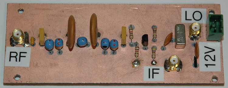
Photo 1 Assembled
receive converter.
Low
Pass Filter
With
the 630 metre band being so close to the AM broadcast band it necessary
to provide a low pass filter to attenuate potentially strong signals
that may desensitise the receiver. AADE Filter Design 4.5 was used to design and analyse
the receiver's low pass filter stage.

Fig 2 AADE Filter Design
4.5 attenuation analysis of the receiver low pass filter circuit.
The real world filter circuit assembly
was testing and exhibited an attenuation curve approximately 25kHz
higher in frequency as compared to the model. See Fig 3. The higher cut off frequency of the
low pass filter was surprisingly high as the AADE Filter Design 4.5
application had generally provided fairly accurate modelling of
similar filters, however the resulting low pass filter performance is sufficient
for the proposed receive converter. The variation in modelling when
compared with the physical circuit performance may be a result of the
use of the cheaper Epoxy
Dipped RF Radial Chokes.

Fig 3
Low Pass Filter attenuation
measurements graphed with excel.
TOP
OF PAGE
Page
last revised 12 March 2022
|