|
TRAVELLING WAVE ANTENNA
Multi-band
travelling wave antenna for portable operations.
With
the view to establish a quick and easy multi-band antenna deployment
for portable and camping operations a travelling Wave Antenna with an
earth with and 9:1 voltage
unun is one possible solution.
Description

Figure
1
Multi-band
travelling wave antenna with an earth or earth plus counterpoise and
9:1 voltage unun.
Configuration includes end termination resistor.
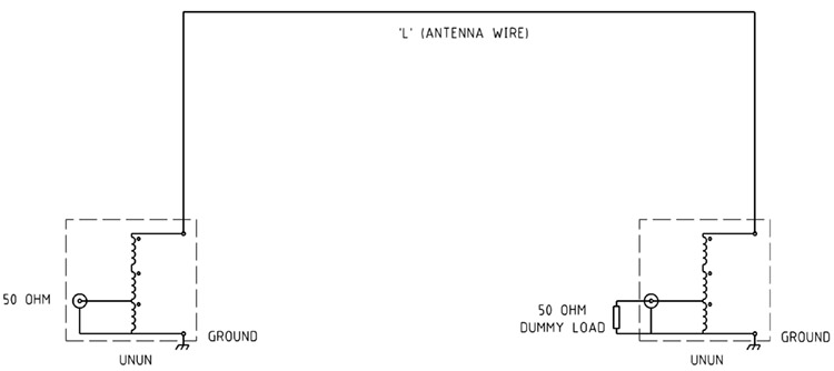
Figure
2
Multi-band
travelling wave antenna with an earth or earth plus counterpoise and
9:1 voltage unun. Alternate
configuration includes end 9:1 voltage unun and 50ohm dummy load
termination resistor.
Features
Ground
terminated TWAs make very good
receiving antennas because the terminations
prevent any static build up on
the antenna wire, keeping the noise level
low.
Construction
The
resistor
terminator
which are used to terminate
the far end of each leg of the antenna
to ground. .
Each Terminator' should have a wattage rating of at least 40%
of the transmitter PEP for voice transmissions
or 80% for continuous transmission. The amount of power
dissipated in the Terminators'
depends on the length of the antenna and the frequency in
use. The shorter the antenna or
lower the frequency, the
more the Terminators' become
the 'Dummy Load'.
Text
References
The
ARRL Antenna Book.
http://en.wikipedia.org/wiki/Traveling_wave_antenna
The
above radiation plots were produced using MMANA-GAL Antenna Analyser
software by JE3HHT, Makoto (Mako) Mori at http://hamsoft.ca/
TOP
OF PAGE
Page
last revised 12 March 2022
|


