|
SOUND CARD INTERFACE
This computer
sound card interface was constructed and refined for use as a
flexible interface between the computer and the TS430 HF transceiver
at my previous residence in Melbourne, Victoria
from 2005 - 2007
Presented
here is a transceiver to computer sound card interface complete with
automated transmit key function. A sound card interface is simply
the audio coupling of a computer soundcard and a transceiver to
allow various computer applications that send and receive SSTV, RTTY,
PSK31 and other similar modes based on soundcard generated signals.
The
interface is designed to be left inline with the ability to easily be
switched between phone and data operations. This version is my first
attempt to interface a computer soundcard with my Kenwood TS-430
transceiver and it has proven to be very successful and easy to
operate.
While
designed specifically to be connected to a Kenwood TS-430
transceiver the design should suit many other Kenwood radios with
little if any modification and should be in principle adaptable to
many other radio types.

Design
The
design is based on the variety of similar circuit that can be found
on the internet to produce a model that is suited ideally to my
needs.
One
of the main aims of this circuit was to develop a simple method of
switching too and from normal voice communication and a range of
digital modes at the flick of a switch.
The
circuit design is however fundamentally about transferring a clean
and undistorted signal between computer and radio. Preventing
unwanted signals, noise and even damaging voltages passing between
the computer and the moderately powerful HF transceiver can be quite
difficult. At 100 Watts the Kenwood TS-430 may introduce RF feedback
into sensitive audio circuits within the radio via connecting leads,
other attached equipment and the computer may find a path to
introduce noise into the sensitive HF receiver.
Audio
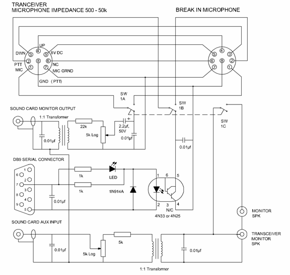
isolation transformers are placed in both, transmit and receive
audio circuits to eliminate the possibility of ground loops. All
cabling between equipment is shielded
audio cable and small value capacitors are place around the circuit
to suppress any stray RF that may have been picked up. An Optical
coupling IC package is used to isolation the transmit PTT
(Push To Talk) keying circuit and the DB9 comms port.
The
both transformers are common 3k to 3k ohm impedance (1:1) audio
transformers complete with a simple
resistor and trim pot attenuation networks to reduce and allow
adjust of the signal levels. The amplitude of soundcard signal to
transceiver microphone input has been shown to require an
attenuation of around 33dB and the transceiver speaker output to
soundcard AUX input requires an attenuation of around 25dB.
I have chosen to arrange the
circuit so that the attenuation is achieved after the signal has
passed through the transformers, with the view that the transformers
may be susceptible to coupling with strong unwanted external
signals. This would leave the ratio of desired signal to unwanted
induced signal at its greatest in this configuration.
The
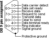
transmit key function requires that the RTS (Request To Send) Pin 7
and Ground Pin 5 from the computer com port be relayed via a 4N25,
or 4N32 Optocoupler chip to the transceiver PPT pins for additional
isolation. Also included is LED transmit key indicator.
Construction
The
unitís components have been laid
out on a section of versa strip board and assembled in a
sealed polycarbonate box, size 115 x 90 x 55
(Dick Smith Electronics) H2863) which is a nice quality box. The positioning of
the components is not critical, but as always neatness counts and
makes it easy to keep track of where you during assembly. Internal
signal wire pairs are twisted to further reduce unwanted signal pick
up.
Short
screened leads connect the computer to the interface and the
location of the device in relation to other station equipment like
the ATU, power supply etc. are all crucial to mitigating stray
signal pick up.
The
computer's CRT screen is a bad source of radio hash and while I
have operated these modes with a CRT screen its replacement with a
new LCD display removed near all the noise from the shack.

Schematic of the interface
between my computer sound card and TS-430S HF transceiver with
computer communications port (9 pin port).

Operating
Once
the interface is inline the first thing to do is set the trim pots
to a useful level with the mic gain and the AF gain in the nominal
position so that when switching from phone to data the levels will
be about right.
The
mic gain will still need to be adjusted to achieve the final
transmitter output power level. This is critical for if the
transmitter is over driving it will result in a lot of adjacent
channel interference and possibly damage to the transmitter.
For
SSTV, the generated signal is a frequency modulated tone causing a
normal SSB transmitter to work hard, exceeding its nominal duty
cycle. Therefore it is recommended that the transmit power be wound
back to around twenty watts for the average 100W HF SSB transceiver
or to about the AM rating of the transceiver. Be conservative!
With
everything adjusted, the interface can be left switched to phone for
normal voice operations where the microphone controls the PTT
function or switched into the data mode where the monitor speaker is
switched out (No noise) and the computer software operates the PTT
function. Even in the phone mode the soundcard is monitoring the
audio, which can be useful.
This
simple but effective means of interfacing radio and computer and the
related software may open up a whole new radio communication
experience if you have not already tried it!
Related
sound card interface site. See:
http://www.qsl.net/wm2u/interface.html
General
sound card information
and standards. See:
http://en.wikipedia.org/wiki/Sound_card
TOP
OF PAGE
Page
last revised 12 March 2022
|