|
6M BAND RINGO
ANTENNA
Reworking of an old 2m band ringo antenna for the
6m band.
Having a small collection of radio equipment for this fascinating band but lacking any suitable antennas, it was time to address this issue.
The antenna was built using an old Cushcraft 2m band co-linear Ringo antenna, which was then converted for the 6m band. This conversion involved reconstructing the matching ring and modifying the 2m band co-linear main element to a single 0.548 wavelength (3.61m) element. The length of the radiating element was determined through antenna
modelling using MMANA, optimising for the best horizon radiation pattern and SWR match.
Construction:
The antenna was assembled using the remaining components of the old 2m band Ringo antenna, specifically the radiator mounting hub and matching ring mounting hardware. Some of the
aluminium tubing from the original main radiating element was reused, along with an additional 1.8m length of 10mm diameter
aluminium tubing, to create the new 3.61m main radiating element. The table below, along with Figure 1 depicting the Ringo drawing, displays the element dimensions for various bands.
| Band: |
6m |
4m |
2m |
| Frequency
MHz: |
52.0 |
70.0 |
146.0 |
| Main
Element Length in mtr 'A' : |
3.162 |
2.306 |
1.105 |
| Ring
Diameter in mtr 'B' : |
0.321 |
0.239 |
0.114 |
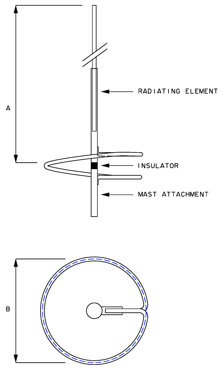
Figure
1
Ringo
element dimensions

Photo
1
Matching
Ring assembly.
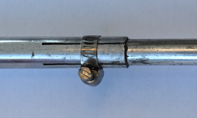 Photo
2
Main element tube sleeve connection. 
Photo
3
Antenna
mounting and 1:1 chocking balun. 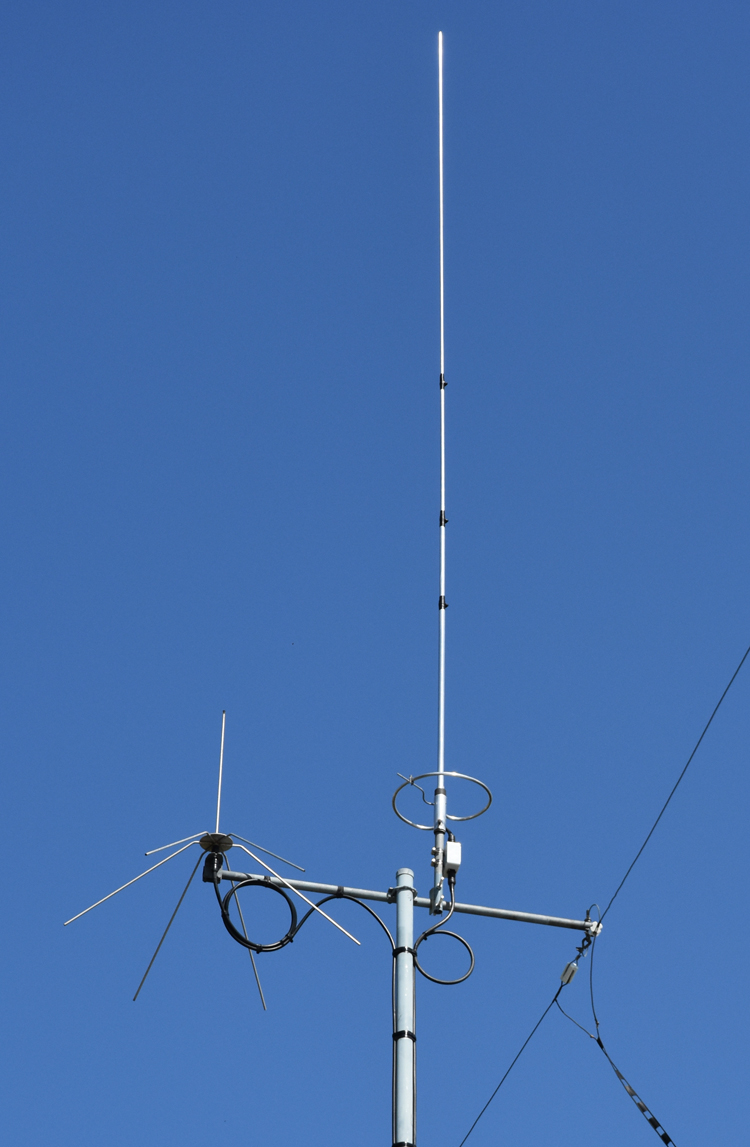
Photo
4
Complete antenna
installation

Figure
2
Radiation
plot for 52MHz were produced using MMANA antenna modeller and optimiser.
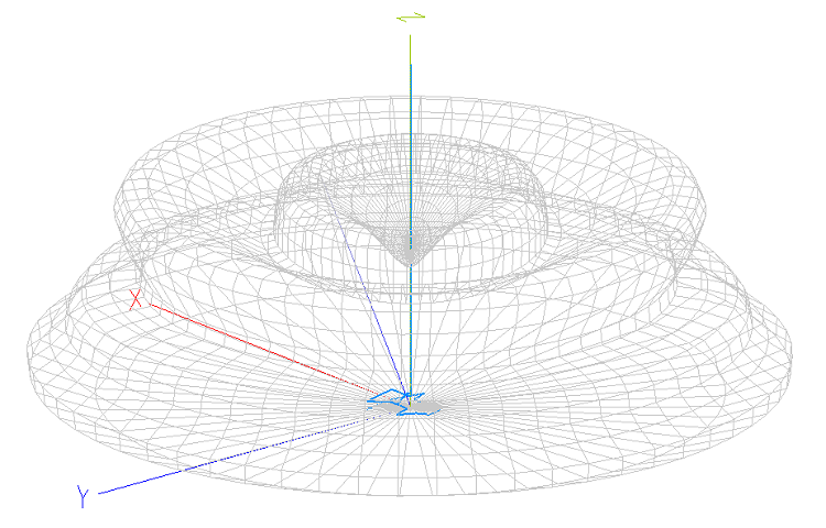
Figure 3
MMANA
antenna model showing the a suitable 3d radiation pattern.
Antenna testing
With the antenna assembled on a readily accessible test mast, positioned well above the ground and clear of any surrounding metallic objects, it was connected to an AIM 4170C antenna
analyser to assess its performance.
The objective here was to achieve the lowest SWR (Standing Wave Ratio) for the operating frequency of 52.0MHz and ideally have the resonant frequency as close as possible to this target.
The AIM 4170C antenna analyser provides a comprehensive display of all relevant data and, importantly, allows the analysis to be projected to the antenna end of the coaxial cable, providing a more accurate representation of the antenna's characteristics.
By making modest adjustments to the matching ring tap, an SWR of 1.7 was achieved at 51.3MHz, with the resonant frequency measured at 52.0MHz. The SWR remained acceptably low across approximately 2MHz of the 6m band, with a maximum of 3.0 observed at 54.0MHz. The phase angle, depicted in purple, revealed a shallow zero-angle crossing at 52.0MHz, indicating the resonant frequency of the antenna.
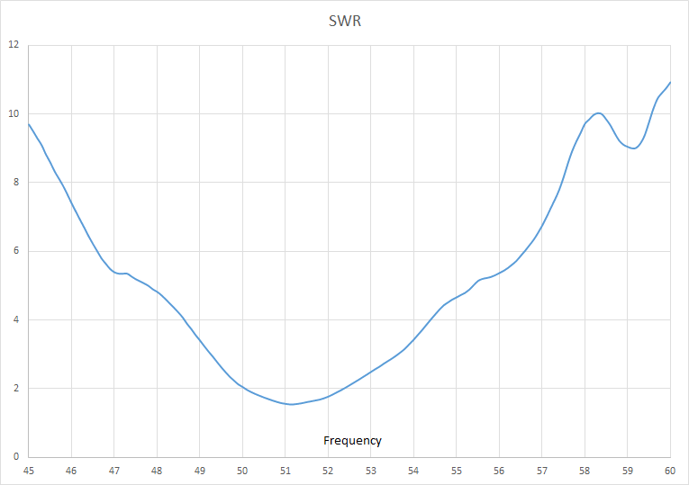
Figure 4
SWR
measurements from 45 to 60MHz
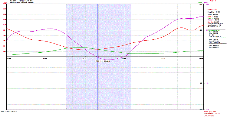
Figure 5 AIM 4170C antenna analyser
measurements from 45 to 60MHz
1:1
Choking balun low band VHF
Choking balun
for lower band VHF. (14 ~ 54MHz)
FT140-43
Ferrite Toroid Core.
TOP
OF PAGE
Page
last revised 11 September, 2018
|