|
ANTENNA
/ RADIO SWITCH
RF
3 position switch for either antenna switching or transceiver
switching 0 - 150MHz.
Needing an RF switch
to switch a single antenna between three 2m band radios, it was
essential to design a system that achieved high switch port
isolation. While switch port isolation is not as crucial for
switching between antennas, it becomes important when transmitting
from one port, as the ports that have receivers connected, even when
turned off, need to be well isolated from RF leakage.
With this in mind, the specifications for the switch include a
maximum RF power of 25 watts at a maximum frequency of 150 MHz.
Additionally, a 12V DC switched circuit is included for a masthead
pre-amp.
The specific requirements for the switch are as follows:
Maximum RF power: 25 watts (44 dBm)
Maximum frequency: 150 MHz
Minimum port isolation: -36 dB
It is important to note that these specifications are based on Ian
(W2AEW)'s presentation on issues related to using an antenna switch
to switch radio transceivers.
Refer to video link: https://www.youtube.com/watch?v=lMMql1gEORQ
The video suggests
that many ham radio transceiver receivers are capable of
withstanding up to +20 dB (100 mW). However, as a matter of caution,
Ian (W2AEW) decided to base his calculation on +10 dB (10 mW). It is
important to note that even +10 dB may still be too much for certain
receivers, such as scanners. Therefore, it is advisable to study the
equipment specifications to determine their suitability.
Radio
specification examples
· The
Icom IC-706MK2G transceiver's service manual, on page 1, states,
"DO NOT apply an RF signal of more than 20 dBm (100 mW) to the
antenna connector. This could damage the transceiver's front
end."
The RSP1 SDR radio, as mentioned on page 5 of its manual, specifies
that "In any configuration, the maximum input power to the RSP1
must not exceed 0 dBm."
Furthermore, the HackRF One has a maximum RX power of -5 dBm. It is
crucial not to exceed this limit as doing so can result in permanent
damage.
It is essential to carefully adhere to these power limitations
specified in the respective equipment manuals to avoid any potential
harm or damage to the devices.
Calculations
A 25W transmitter
would represent 44 dB. Therefore, the calculation would be 44 dB
(25W) - 10 dB (safe receiver exposure) = 34 dB (minimum required
port isolation). Based on this calculation, the RF switch meets the
required port isolation at the desired 146 MHz (2m band). However,
it would not be suitable for higher power levels in the 2m band or
for higher frequencies such as the 70cm band, even at realistic
power levels.
Below 54 MHz, sufficient port isolation would allow for a 100W
transmitter to be used. However, it's important to note that the
current rating of the wafer switch used would likely not support
power levels much beyond approximately 100W.
It's crucial to consider these factors when assessing the
suitability of the RF switch for specific power levels and frequency
ranges.
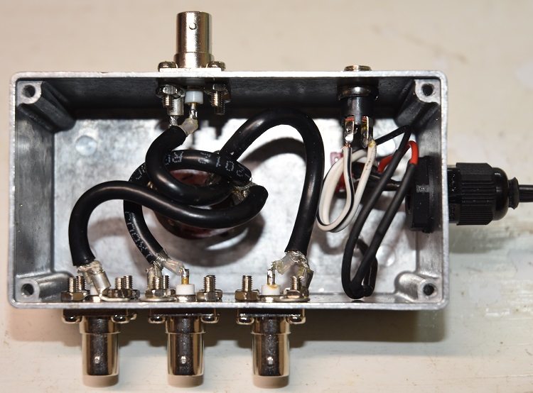
Construction
The switch is a
simple 3-position, single-pole wafer switch. All lead connections
between the wafer switch and BNC bulkhead mounts are made using RG58
coax. The coax shield braid is soldered together at the wafer
switch, and the centre core connections are kept as short as
possible, around 6mm (1/4").
The 12V DC switched circuit for a masthead pre-amp has a short tail
with a 30A Anderson connector and a 2.1mm DC panel socket.
Testing
Test was carried out
using a NanoVNA calibrated for Mag with the switch switched to an
adjacent port with a 50ohm load connected. The below results and
chart show port isolation against various frequencies.

|
Frequency
MHz
|
Port
Isolation dB
|
|
1.000
|
-70.00
|
|
3.500
|
-65.00
|
|
10.000
|
-59.50
|
|
15.000
|
-56.00
|
|
30.000
|
-51.50
|
|
54.000
|
-46.50
|
|
146.000
|
-36.70
|
|
435.000
|
-25.00
|

TOP
OF PAGE
Page initiated 26 June,
2022
Page
last revised 18 August, 2023
|