|
KEEPING RADIO ALIVE
Article of a personal journey of radio repair and restoration.
Published in the WANSAC (Western
& Northern Suburbs Amateur Radio Club) monthly club magazine Vol
? Issue August 2025
http://www.wansarc.org.au/
Keeping the Radios Alive: A Personal Journey of
Repair and Restoration
By
Peter Miles – VK6YSF
Like many radio amateurs, I’ve had a wide variety of radios pass
through the shack over the years—most acquired opportunistically,
often because the price was right. My journey with radio equipment
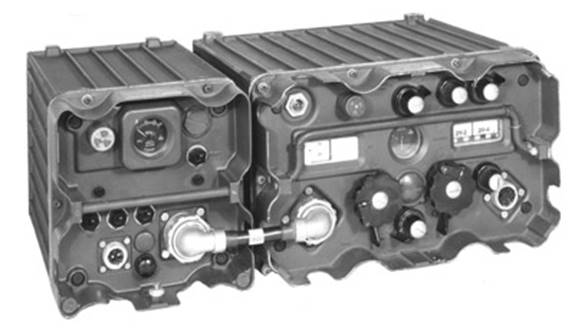
began back in 1980 with a C42 military transceiver, a big, clunky
beast that covered roughly 35 to 60 MHz and produced a massive 10
watts of RF. It wasn’t exactly built for amateur radio use, in
fact it only really could communicate with other C42 radios due to
the extreme FM deviation, but it served nicely as in introduction to
the 6-meter band and was a lot of fun as there were a lot of these
radios dumped into the market at the time, so there were plenty on
contacts to be had. This radio was also my introduction to the
technical side of the hobby: adapting what you had to do what you
wanted.
Over time, I ended up with a fleet of radios that, curiously enough, were
all built between the early 1980s and mid-1990s. Again, this was
less about deliberate choice and more about opportunity. But in
hindsight, there was something fortuitous about it. Radios from that
era struck a sweet spot between performance and maintainability.
Moving West
In 2007, I moved from Victoria to Northam in rural Western Australia for
work. This move also saw a shift in my radio activity. With a bit
more space and time, I got more active on the air again. I’d
collected a nice range of radios by then - ones I genuinely enjoyed
operating. To me, these weren’t boat anchors; they were just the
radios I used: a Yaesu FT-736R for VHF/UHF, a Kenwood TS-430S, and a
TS-930S for HF.
Then disaster struck. One by one, every radio failed - each with its own
unique and serious issue. Within a short window of time, my entire
station was silent. My first thought was to get them repaired.
Surely, someone in the state could help. But that search turned up
empty. The few repair techs I could locate were on the east coast or
even overseas. Shipping heavy radios across the country or
internationally just wasn’t practical, especially on a
hobbyist’s budget.
The idea of abandoning the hobby altogether crossed my mind.
Choosing to Fix What I Couldn’t Break Further
After some soul-searching, I reminded myself why I’d gravitated toward
these particular radios in the first place - they could be fixed.
And really, I had nothing to lose. The radios were already
non-functional. I couldn't break them worse.
So I committed to repairing them myself. Not with blind optimism, but
with a methodical mindset. That became my mantra: don’t grab
the soldering iron until you fully understand the fault.
My Repair Process
I began by studying block diagrams, isolating faults by functional area.
Where is the signal chain failing? What’s working and what
isn’t? I applied divide-and-conquer logic, studied schematics in
detail, read what I could find online, measuring and testing. And
when I had doubt - I backed up a step.
In almost every case, the key lesson was this: the hard part is identifying the fault, not fixing it. I’d
estimate 90% of the work is in diagnosis, and only 10% is the actual
repair.
Repair Highlights
Yaesu FT-736R
The FT-736R VHF/UHF
transceiver developed a start-up fault that manifested as a
momentary flicker of the frequency display and other instrumentation
backlighting, or a failure to start altogether. Upon pressing the
power button multiple times, the radio would eventually start up and
operate normally. This fault appeared to be identical to a common
power supply issue that had been identified for this particular
radio. Convinced that this was indeed the problem, I planned to
carry out the recommended power supply repair, which involved
replacing the power supply electrolytic capacitors and re-soldering
any heat-stressed connections on the power supply PCB.
During one instance of powering the
radio up, it started normally without any flickering of the
instrumentation lights. However, there was no audio output, not even
a click, when powered up or when the mute function was opened. The
fault that had affected the receiver/audio had also caused the power
supply to trip off until the fault finally cleared itself through
destructive means. The audio board was suspected to be the faulty
section, and using a sniffer audio amplifier, I sampled the audio
signal into the AF board and detected good, clean audio when opening
the mute. The fault has now been isolated to the AF board.
Subsequently, the AF board was replaced with a new one, and the
radio is now fully operational.
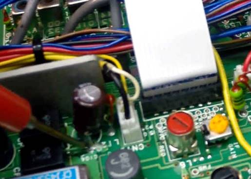
The faulty AF board
has been repaired and kept as a spare. Further investigation
revealed that the R30 resistor (1 ohm 0.25 watt) had open circuited,
likely due to a failure of either the C20 electrolytic capacitor
(2200uF) or the Q06 amplifier chip, which caused excessive current
flow through the resistor.
Although the C20 electrolytic
capacitor seemed fine based on capacitance measurement and leakage
test, it was still replaced due to its age and the possibility that
it could have been the source of the problem.
The R30 resistor (1 ohm 0.25 watt) is
apparently a known issue with this radio and can fail on its own,
likely due to being under-rated for its location in the circuit. The
R30 resistor was replaced with a 1.0-watt resistor. The power supply
tripping indicated that there were other factors at play, possibly
related to the C20 electrolytic capacitor.
In the end, the radio
is now operating normally, and a good spare Audio board is
available.
What I learnt; despite having successfully completing the repair,
I had over reacted and got into solution mode without fully
understanding the fault and had made a relatively small repair into
a larger more expensive repair.
Kenwood TS-430S
The TS-430S is an
iconic HF transceiver from the mid-1980s. Despite having had several
owners, this particular radio is in moderately good condition, with
all knobs and markings intact.
However, in recent times, the radio has
developed various issues in both receive and transmit functions,
rendering it completely useless. These are common problems not only
with this model but also with many similar models from the same era.
The radio exhibits slow start-up and stabilization, along with an
unstable tone in the receive audio. The receiver's sensitivity has
significantly decreased across most of the band pass filter groups.
Additionally, the transmitter experiences intermittent power level
variations, and the VFO is unstable.
List of
issues requiring attention
The radio is slow to start up and stabilise.
There is an unstable tone present in the audio.
Receiver has low too very low sensitivity on most of
the band pass filter groups.
The transmitter has intermittent power output.
The S meter is very unresponsive in most receive
modes except FM.
The VFO is often unstable.
The S meter back light failure.
Superficial paint damage.
Measure Receiver Sensitivity and Maintenance of the Filter Unit
Board Repair
The
receive issues were tackled first, and the first step involved
measuring the current MDS (Minimum Discernible Signal) level on all
bands to establish a benchmark for any improvements. Receiver
sensitivity figures are typically expected to be better than -120
dBm, while MDS levels of -60 dBm indicate extremely poor
performance, effectively rendering the receiver deaf.
The TS-430S Filter Unit board switches various bandpass filters
using relays, and the MDS results obtained clearly indicate that the
tested frequency groups correspond to the various bandpass filter
ranges. This provides strong evidence that oxidized relay contacts
are the likely major cause of the poor receiver performance.
Receiver Sensitivity Repairs
The
Filter Unit (X51-1290-00) was removed from the radio for detailed
inspection, and the contacts of relays RL1 to RL15 were cleaned by
wiping them with a small sliver of gloss paper soaked in contact
cleaner. Gloss paper was used to avoid being too abrasive on the
silver-plated contacts, and the choice of gloss paper ensured that
no paper fibres would be left behind to disrupt ideal electrical
contact.
All plugs and sockets on the Control Unit (X53-1290-000), IF Unit
(X48-1370-00), Control Unit (X53-1290-00), RF Unit (X44-1510-11),
and FM Unit (X48-1340-01) were unplugged, cleaned with contact
cleaner, and re-plugged. This process was repeated several times to
ensure good electrical contact. Additionally, the RL1 relay on the
RF Unit (X44-1510-11) was cleaned, similar to the Filter Unit
relays.
The results of eliminating all the poor electrical contacts within
the radio were significant: the radio regained full receive
sensitivity, and the power and signal strength meter started
providing meaningful readings again. Furthermore, the transmitter
regained stability.
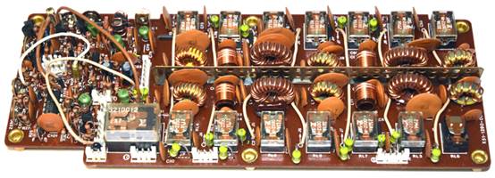
Filter Unit (X51-1290-00) board layout
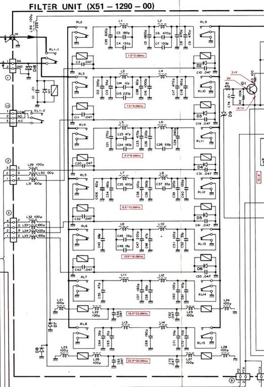
Filter Unit (X51-1290-00) relay section
schematic
Unstable tone present in the audio during start up.
The
receiver experiences a strong, unstable, and highly irritating tone
during start-up, which gradually diminishes over a period of 5 to 10
minutes but never completely disappears. During this time, the tone
registers around S10 on the signal strength meter, and the
receiver's sensitivity is significantly compromised.
Upon conducting the initial inspection of the radio, it was observed
that the IC9 5-volt regulator chip on the IF Unit (X48-1370-00) was
excessively hot to the touch. The IC9 regulator is responsible for
supplying power to the frequency Display (X54-1630-00) board. By
touching the area surrounding the IC9 regulator and the wiring
connected to the Display board, it was found that the annoying tone
would change in both amplitude and frequency.
Repair
All
the electrolytic capacitors on the Display (X54-1630-00) board have
been replaced, but there has been minimal improvement in the tone.
However, the tone now completely disappears after the 5 to 10 minute
period, whereas previously there would often be a small residual
tone remaining. The replacement of the electrolytic capacitors is
generally beneficial, as they can be potential failure points in
older radios.
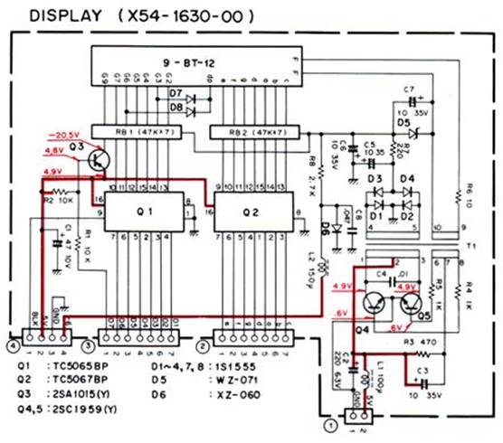
Display (X54-1630-00) schematic
The electrolytic capacitors C118 and C119 on the IF Unit (X48-1370-00)
board have been replaced and the IC9 AN7805 5 volt regulator has
also been replaced with a LM7805CT.
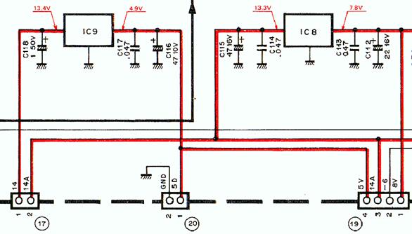
IF Unit (X48-1370-00) 5 and 8 volt regulator section schematic
The
replacement of the above-mentioned electrolytic capacitors has
resulted in the complete disappearance of the unstable tone during
start-up, and the radio now starts up perfectly without any signs of
instability. Surprisingly, the instability with the VFO has also
completely disappeared.
Replacement of the TS-430S meter backlight with new bright LED

TS-430S backlit display
The incandescent
meter backlight had failed and required replacement. While a simple
like-for-like replacement was possible, a much superior solution was
available with bright LED (Light Emitting Diodes) lamps. LEDs have
many superior characteristics compared to traditional incandescent
lamps, particularly in terms of reliability. However, they may not
always be an ideal solution. One key performance difference is that
LEDs radiate light forward in a narrow beam of between 10 and 20
degrees, unlike the more omnidirectional pattern of most
incandescent globes. Therefore, if the backlight relies on a more
omnidirectional light, the replacement process is not as
straightforward as simply replacing the existing incandescent globes
with newer LED lights.
Fortunately, the TS-430 radio is well suited for LED backlighting
for the meter. The 5mm LED is a good physical fit, and the tight
angle of the LED is well suited to the display light guide. The
TS-430 radio's dial light is powered by a 13.8V DC supply. It was
found that using 1.2k ohm 0.25 Watt resistors in series with the 5mm
White, 45000mcd LED provided good results and a lower running
current. The 1.2k ohm current limiting resistor should provide a
very reliable, long life for the LED.
The 5mm LED
snugly fits into the existing rubber grommet and can be slightly
adjusted for optimal effect.
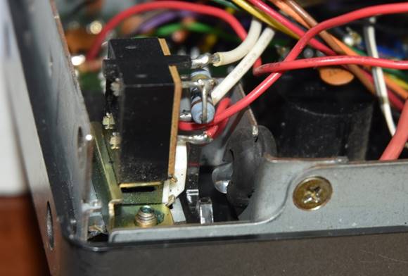
The 5mm LED fitted in the exiting rubber grommet and
mounting bracket.

Fully Repaired and Restored Kenwood TS-430S
What I learnt; this repair or restoration was a high watermark as
while there were a number of misdiagnosis I remained open minded and
kept my options open. No further damage was made and no excessive
repair solution carried out.
The radio looks
fantastic and has been working well since and is still main radio
that is operated regularly.
Only a second
cleaning of the relay contacts was carried out about 5 years later.
Kenwood TS-700SP
Symptom: Complete and total loss of receiver
sensitivity.
Repair: The identified fault was oxidation of the DX switching
relay contacts, which are located on the RX NB Unit. After applying
a small amount of contact cleaner to the relay contacts using a
strip of glossy paper, the radio receiver regained full sensitivity,
including the on-board low-noise pre-amplifier that hadn’t worked
for years.
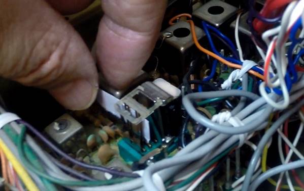
DX switching relay contacts cleaned with a
strip of gloss paper and contact cleaner.
What I learnt; fearing the worst, probing and measurements and a bit of
tapping narrowed the fault down to relay contacts. Again showing
that faults are often ridiculously simple.
Kenwood TS-450S
Symptom: Complete and total loss of audio.
The radio was purchased after a quick power-up test,
which produced a healthy loud white noise and all displays lit up.
However, when the radio was powered up at home, there was no audio.
Although all displays appeared to be working well and the S meter
showed full deflection to an obvious signal.
While using a sniffer amplifier to probe the input
pin 1 at IC5 (uPC2002v audio amplifier chip) it was noticed that
there was goo around the base of electrolytic capacitor C104.
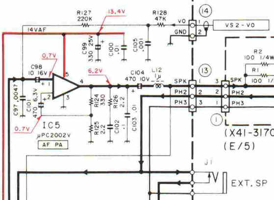
C104, a 470uF electrolytic capacitor, had
catastrophically failed, causing the electrolyte material to blow
out from the bottom of the capacitor and onto the PCB (Printed
Circuit Board). The damaged C104 capacitor was replaced, and the
electrolyte material was thoroughly cleaned from the board. The
electrolyte had reacted with the green PCB mask, resulting in
complete deterioration of the mask under the capacitor and leaving
the exposed copper after cleaning.
There is a
reasonable concern that the electrolyte material would have
ultimately corroded the copper PCB tracks.
After
replacing C104 and thoroughly cleaning the electrolyte material,
related electrolytic capacitors C99 and C101 were also replaced as a
matter of opportunistic preventive maintenance while the board was
out.
The radio
was powered up and worked perfectly.
What I learnt; keeping eyes open, a fault can sometimes be identified very
quickly.
Outcomes and Reflections
Repairing these radios wasn’t easy, but the satisfaction was immense.
Not only did I restore valuable gear, I gained what is known as
experience that’s proving useful in other areas too. I’ve now
begun working on construction projects that involve surface-mount
components - assembled under a microscope - something I never
would’ve attempted a few years ago.
I’ve learned that many faults that seem complicated are just poor
connections: oxidized relays, dirty plugs, and aging capacitors.
With methodical analysis and a willingness to learn, almost anything
can be fixed.
In the end, these experiences gave me much more than working radios. They
gave me confidence, skill, and a deeper appreciation for the art of
repair. I no longer see a broken radio as a burden - I see it as an
opportunity. And like so many challenges in amateur radio, what
starts as frustration can end in reward if you stick with it.
Peter VK6YSF
This article was based on a talk that I did at Perth Tech in 2024
Reference of details of the repairs discussed.
FT-736R - F2887103A audio board fault location and repair.
FT-736R
- AF Board Repair
Kenwood TS-430S Repair and Restoration.
TS-430S
Repair
Kenwood TS-700SP receiver repair.
TS-700SP
Repair
Kenwood TS-450S audio repair.
TS-450S
Audio Repair
TOP
OF PAGE
Page initiated 04
August, 2025
Page
last revised 05 November, 2025
|