|
MULTI-BAND HF LINKED SECTION GROUND
PLANE ANTENNA
Mult-band
HF
portable linked section ground plane antenna - 14 MHz to 28MHz. October 2025.
For portable HF operation, flexibility and simplicity are essential. This multi-band ground-plane antenna covers 14 to 28 MHz (20 m to 10
m Bands) using a compact, lightweight design that can be deployed quickly in the field.
The antenna uses detachable link sections in both the radiator and the three ground-plane radials, allowing the operator to easily configure it for 14 MHz, 18 MHz, 21 MHz, 24.9 MHz, or 28 MHz, depending on which links are open.
Designed to mount on a 7-metre fibreglass pole, the antenna performs efficiently while keeping
set-up time to a minimum. The three radials form an elevated ground plane, positioned about 1 to
2 metres above ground level for optimal radiation efficiency and low ground losses.
The antenna operates as a quarter-wave ground-plane on each selected band.
By inserting or removing simple link connectors, each element’s electrical length is adjusted to suit the desired frequency. This method avoids coils or traps and keeps losses low while maintaining mechanical simplicity.
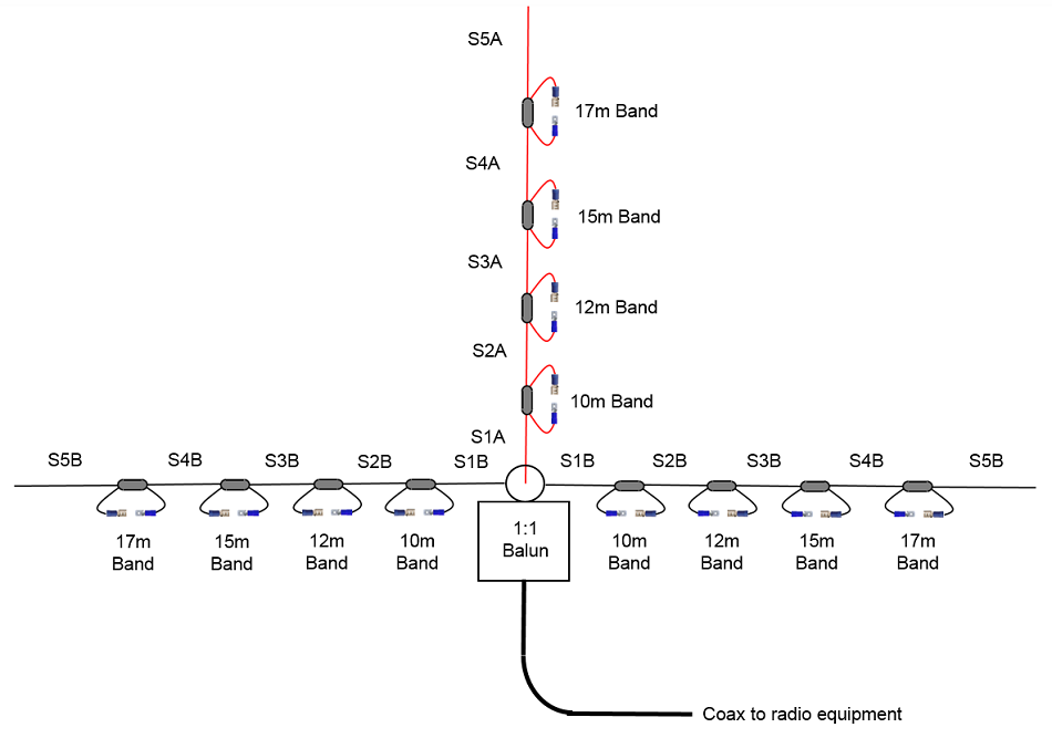
Fig
1 The multi-band ground plane antenna link arrangement.
Note that only two of the ground plane radials are shown and it is
intended that there normally be 3 radials.
When the
radials are not angled down at the more ideal 40°
angle and are more or less flat due to
practicalities of attaching the antenna to a Squid pole for example,
the antenna will be only about 1.5 to 2m above the ground and the
feed impedance will be
much lower than the ideal 50 Ohms. A simple solution is to the prune the
radiator until the best match is achieved and this is likely to be significantly shorter than the calculations would
suggest.
|
Band
|
Frequency
MHz
|
Radiator Length
(mm)
|
Radial Lengths
(mm)
|
|
10 m
|
28.30
|
S1A |
*
2270 |
S1B |
2950 |
|
12 m
|
29.50
|
S2A |
*
360 |
S2B |
420 |
|
15 m
|
21.15
|
S3A |
*
520 |
S3B |
615 |
|
17 m
|
18.70
|
S4A |
*
510 |
S4B |
610 |
|
20 m
|
14.10
|
S6A |
*
1030 |
S5B |
1345 |
Table
1 Shows
the multi-band ground plane antenna element section dimensions. *
Note that the radiator lengths were experimentally trimmed
to these lengths.
Some
limited degree of directivity can be achieved by arranged
the radial elements in a group towards a particular direction
as shown by the below MMANA-GAL antenna
model .
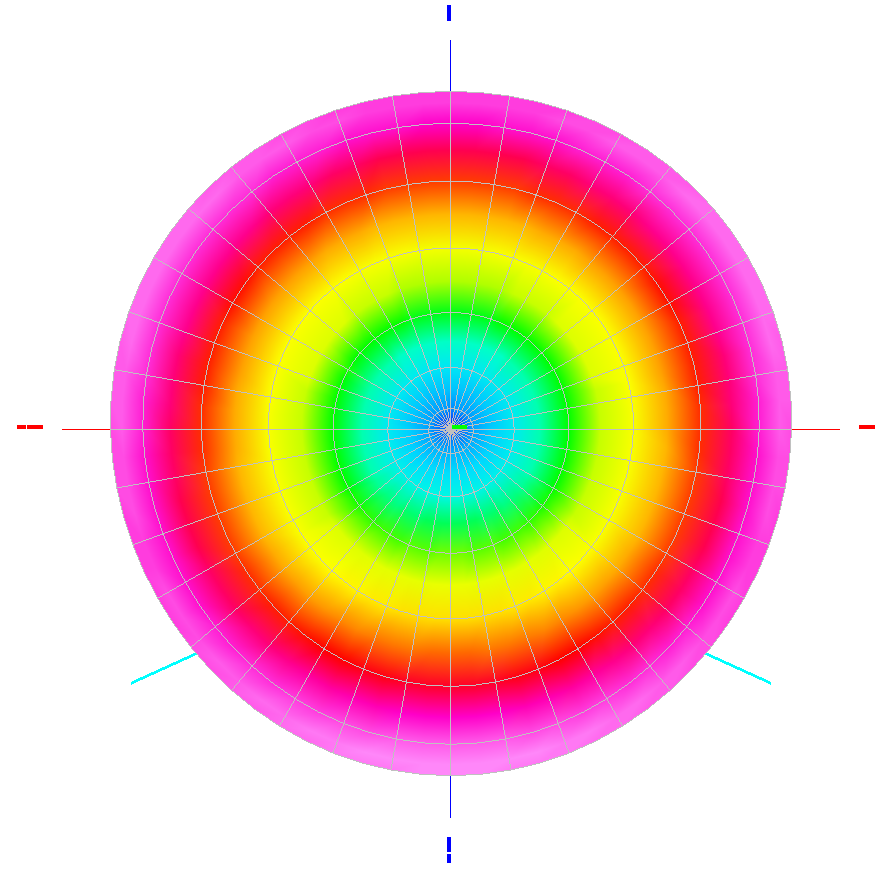
Fig
2 Shown above is the MMANA-GAL antenna
model of a typical omnidirectional radiation pattern of a
ground plane antenna with the radials arranged 120° apart.
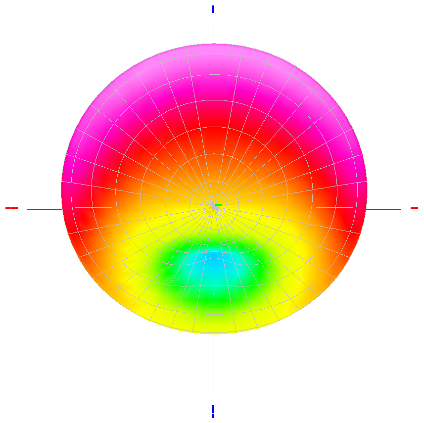
Fig
3 Shown above is the MMANA-GAL antenna
model of the radiation pattern of a ground plane
antenna with the radials arranged in a group pointed towards north
(Up)
Construction Details
The entire antenna is built from readily available materials, making it ideal for
ease of construction and experimentation.
Constructed from PVC-insulated 0.75 mm² (AWG 18/19) stranded copper
wire with each element (the radiator and three radials) being divided into linked sections that can be connected or isolated to set the operating band.
The section insulators are made from 6 mm diameter water reticulation pipe, providing lightweight but sturdy electrical isolation between wire sections.
Each break in the wire is terminated with crimp-type spade lugs forming
a make/break connection.
The male and female spade lugs allow quick reconfiguration: simply unplug to shorten the element for higher-frequency bands, or reconnect for lower frequencies.
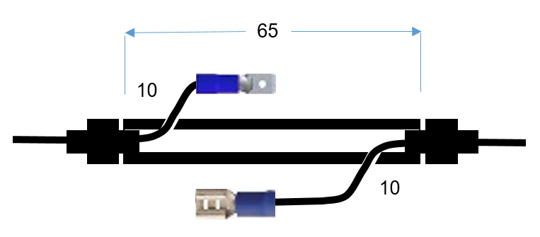
Fig
4 Shows
the make/break
connector arrangement.
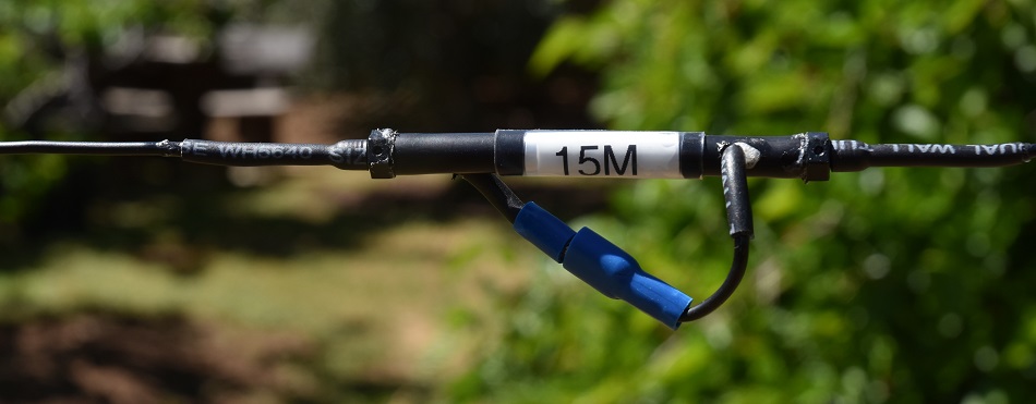
Photo
1 Shows
the make/break
connector arrangement.
Heat-shrink tubing is applied over wire ends and joints to prevent fatigue and protect against moisture ingress.
Short wire pigtails are used at each make/break joint, adding flexibility and strain relief at the connection points.

Photo
2 Shows simple
loop termination.
The
1:1 Guanella current balun is the convenient central hub of the
wire ground plane antenna and while the balun was never designed with
this antenna configuration in mind it works fairly well.
The feed
Impedance should be typically 35 - 70 Ω, depending on radial angle and height.
With the 1:1 current balun provides an effective transition between coax and the balanced ground-plane system.
The balun acts as both feed transformer and choke to suppress RF on the coax
shield with no additional matching network normally required, although slight SWR variation between bands is expected due to element geometry and environmental factors.
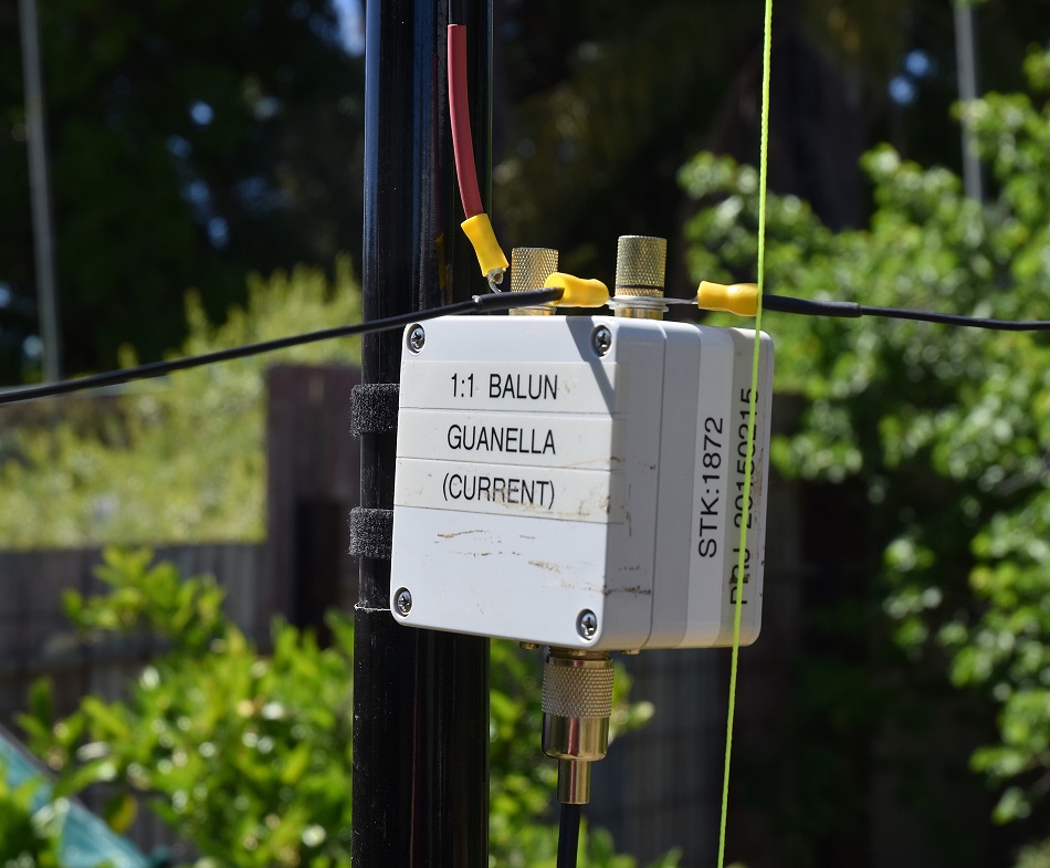
Photo
3 Balun connection
hub.
The radiator wire runs vertically up a 7 m fibreglass pole with the three radials extend outward and downward from the balun hub, spaced roughly 120° apart.
The radial tips are tied off with ropes to pegs or natural supports to maintain a height of 1
– 2 metres above ground.
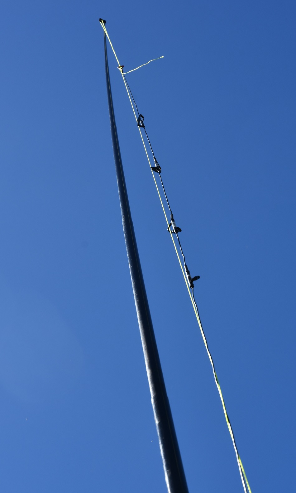
Photo
4 The radiator wire run up the 7 m fibreglass pole
Testing
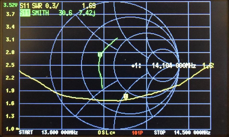
Photo 5
NanoVNA SWR and Smith Chart results, showing the SWR being below 2.5:1 from 13 MHz to 14.5 MHz
with an impedance of 30.6 +7.42j
and SWR of 1.69:1 at 14.104 MHz.
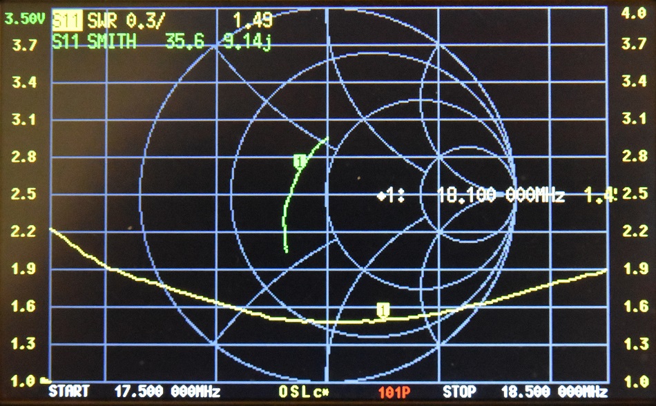
Photo 6
NanoVNA SWR and Smith Chart results, showing the SWR being below 2.2:1 from 17.6 MHz to 18.5 MHz
with an impedance of 35.6 +9.14j
and SWR of 1.49:1
at 18.100 MHz.
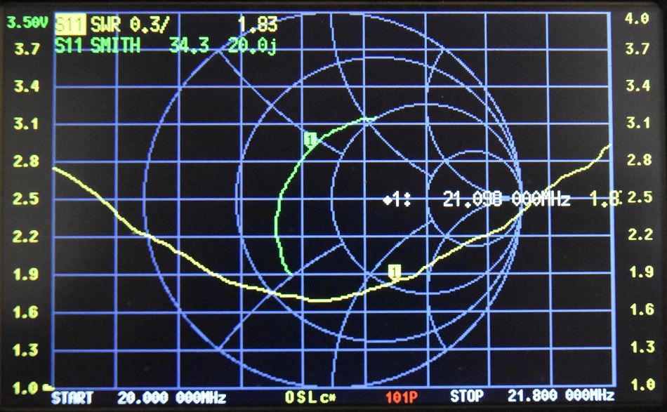
Photo 7
NanoVNA SWR and Smith Chart results, showing the SWR being below 2.8:1 from 20.0 MHz to 21.8 MHz
with an impedance of 34.3 +20.0j
and SWR of 1.83:1
at 21.100 MHz.
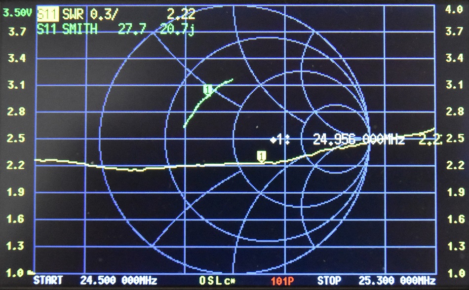
Photo 8
NanoVNA SWR and Smith Chart results, showing the SWR being below 2.5:1 from 24.5 MHz to 25.2 MHz
with an impedance of 27.7 +20.7j
and SWR of 2.22:1
at 24.6 MHz.
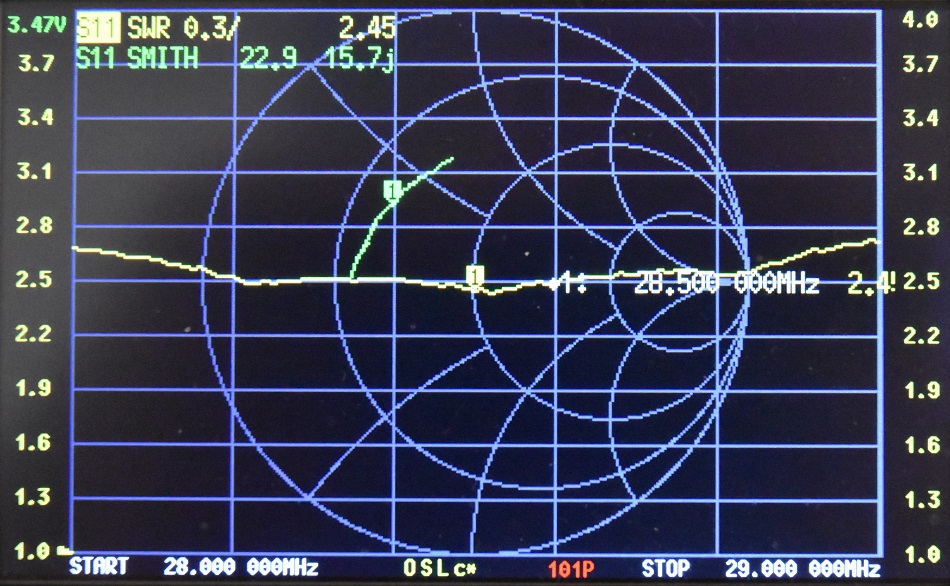
Photo 9
NanoVNA SWR and Smith Chart results, showing the SWR being below 2.8:1 from 28.0 MHz to 29.0 MHz
with an impedance of 22.9 +14.7j
and SWR of 2.45:1
at 28.5 MHz.
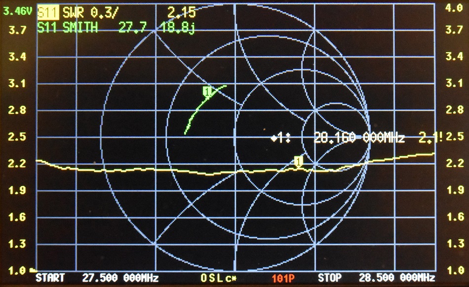
Photo 10
NanoVNA SWR and Smith Chart results, showing the SWR being below 2.4:1 from 27.5 MHz to 28.5 MHz
with an impedance of 27.7 +18.8j
and SWR of 2.15:1
at 28.16 MHz. The different results from testing at 10m by simply
raising the antenna from 1.5m to 2.5m illustrating the effect of
set-up changes.
Performance and Field Use
When set up correctly, this antenna provides efficient radiation at low elevation angles, excellent for long-distance (DX)
contacts and good SWR across each target band with minimal adjustment.
The elevated radial system significantly improves performance compared to ground-level radials by reducing earth losses and maintaining a consistent
feed-point impedance across varying ground conditions.
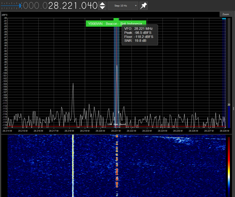
Photo
11 Shown is the YB9BWN beacon in Bali, Indonesia that was sufficiently
stronger than the station antenna, indicating the DX capabilities of
the ground plan antenna.
References
Balun
used for is this configuration is a 1:1
Guanella
Current
balun
using a
L15 ferrite core (1.8 -
30MHz). BALUN
1:1 CURRENT
Makoto Mori. (n.d.). MMANA-GAL antenna modelling software: https://hamsoft.ca/pages/mmana-gal.php
TOP
OF PAGE
Page initiated 03 September, 2025
Page
last revised 29 July, 2026
|