|
MULTI-BAND DOUBLET ANTENNA - HIGH HF
AND LOW VHF
Multi-band
Doublet antenna to cover the 20m, 17m, 15m, 12m, 10m and 6m bands. December 2024.
Requiring
an antenna to cover the 6m band (50 - 54MHz) that is horizontally
polarized and also for coverage of the upper HF bands a 8.6m
multi-band Doublet antenna fed with a section of coax run through
the roof and building wall to a Matching tuner or potentially
directly connected to the radio. The un-balanced coaxial cable is
connected to the antenna with the combination of a 1:1 choking
baluns and a 1:4 impedance step up balun connected in series.
The antenna, feed line, baluns and antenna set-up
is shown in below in Fig 1.
The
1:1 choking balun is to mitigate common mode RF currents on the coax
cable and reduces noise pickup on the coax from within the building
entering the antenna system and also produce a balanced antenna
system that will have a more predictable radiation pattern.
The
1:4 impedance step up balun is included to more broadly match the
range of impedance at the antenna/feed line with the nominal 50-ohm
impedance of the coax.
The
antenna will be formed by cutting insulators into two existing tower
guy wires to create an Inverted 'V' dipole antenna.

Figure
1 Multi-band
Doublet, feed-lines and balun configuration.
Basic
Multi-band Doublet Arrangement.
(1)
Inverted 'V' Dipole. (8.6Mtr total length)
(2)
1:4 Current Balun. See Fig 4 and 5 for details
(3)
1:1 Choking Balun. See Fig 6 for details
(4)
RG213 Coax cable (17m)
(5)
1:1 Choking Balun. See Fig 6 for details
Antenna
modelling.
The
antenna has been modelled with MMANA-GAL
an antenna analyser application to optimise the antenna for the
lower portion of the 6m band. While the modelling gives a bit of
prediction of the antenna performance, the real world site will
likely provide very different results.

Figure 2
MMANA-GAL antenna analyser modelled SWR for the 6m bands when
dipole is matched at 200 Ohms.

Figure
3 MMANA-GAL antenna analyser modelled radiation plot for the 6m bands.
The
above radiation plots were produced using MMANA-GAL Antenna Analyser
software by JE3HHT, Makoto (Mako) Mori at http://hamsoft.ca/
1:4
Current Balun
The 1:4 current balun is derived from two 1:1 current baluns with each consisting of a close double bifilar winding of 3.5 turns wound evenly spaced around
the FT140-61 Ferrite Toroid Cores. The wire is PTFE (Polytetrafluoroethylene) silver plated copper wire, of 1.0mm diameter (AWG 18), and white for this project.
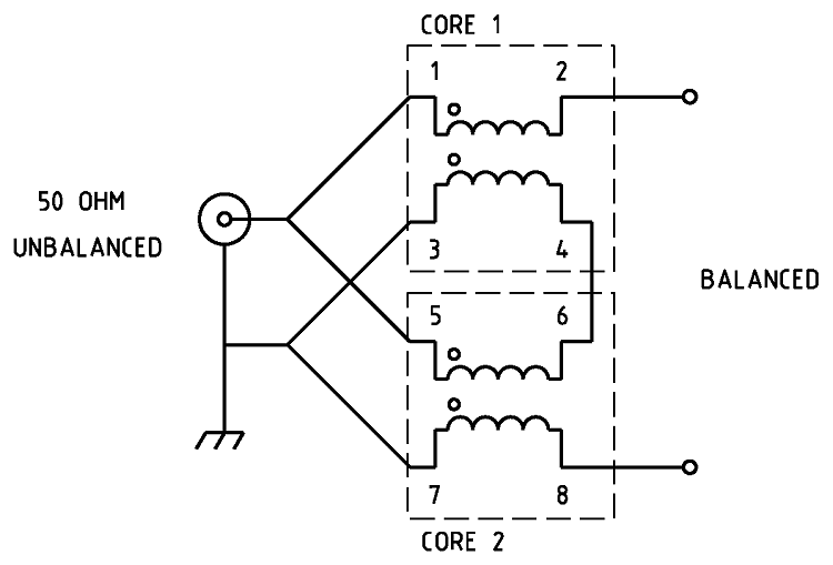
Figure
4 Schematic
of the 1:4 Guanella Current balun
.

Figure
5 Wiring
of the 1:4 Guanella Current balun.
|
Type
|
Impedance
transformation
|
|
Ratio
|
1:4
|
|
Frequency
Range
|
8.0
~ 60MHz
|
|
Core
Used
|
FT140-61
Ferrite Toroid Core x 2
|
|
Number
of turns
|
Core 1 =
4.5
turns x 2, Core 2 = 4.5 turns x 2. PTFE silver plated copper wire, 1.0mm, AWG 18, White. |
|
SWR
|
1.2:1
or less. Ref: Photo 2
|

Photo
1 1:4
balun assembled.
1:4
balun testing

Photo
2 Shows the Nano VNA antenna analyser plot viewing a 200ohm resistive load through the
1:4 balun. Note the 200ohm resistor appears as 50ohms due to the 1:4 balun ratio
transformation resulting in an ideal SWR of 1:1. This plot shows an SWR ranging from
1.0 MHz to 60MHz with a 1.1:1 or better SWR from 10MHz to 60MHz.
While
the core choosing is not ideal it has tested as sufficiently
efficient impedance transformation at the intended power levels of
100w or less.
For
Summary of suitable ferrite cores and core types for a frequency range of 100 kHz to 50 MHz for power levels of 50W, 100W, and 500W continuous and SSB. It assumes good thermal management and proper balun design.
See: Power
- Ferrite Core Design
1:1
Choking Balun
The
choking balun to isolate the potential common mode RF on the coax cable
and to reduce noise pick up.

Figure
6 Schematic
of the 1:1 choking balun
|
Type
|
Choking
Balun
|
|
Ratio
|
1:1
|
|
Frequency
Range
|
14
~ 54MHz
|
|
Choking
Impedance
|
2k
Ohms minimum.
|
|
Core
Used
|
FT140-43
Ferrite Toroid Core
|
|
Number
of turns
|
8
Turns.
(Coax - RG316/U 50 OHM)
|
|
SWR
|
1:1 Ref:
Photo 4
|

Photo
3 Choking balun assembled.
Choking
balun testing

Photo
4 Shows the Nano VNA antenna analyser plot of the choking
attenuation in dB to mitigate common-mode RF current on the coax
shield. 20dB attenuation should be considered the minimum. This plot shows
a choking attenuation
of -29.4dB from 40MHz to 60MHz.
Mast
Head Matching Enclosure.
The
mast head matching transformers are installed in a aluminium diecast
enclosure 160mm x 115mm x 50mm deep. The feed-through insulators are
cemented in place with windscreen sealant.

Photo
5 Mast
Head Matching Enclosure

Photo
6 Feed-through
insulators

Photo
7 Feed-through insulators installed with windscreen sealant.

Photo
8 Mast
Head Matching unit assembly.

Photo
9 Mast
Head Matching unit installed on the mast with the dipole antenna cut
into the guy wires.

Photo
10 Mast
Head Matching unit installed on the mast with the dipole antenna cut
into the guy wires.
TOP
OF PAGE
Page initiated 01
December, 2024
Page
last revised 29 July, 2026
|