|
DC LINE FILTER 12V
DC line filter to mitigate DC supply noise to repeater equipment at
VK6RAV (Hoddys Well)
A
persistent issue has been identified with the VK6RAV VHF repeater,
where a somewhat square wave hum is present in the retransmitted
audio. This interference originates from the 14V regulator in the
solar battery charger and is only present during daylight hours,
confirming its relation to the charging process.
The interference exhibits characteristics of harmonic-rich switching
noise, which contaminates the DC supply and couples into the
repeater’s audio path. The result is a significant increase in
background noise, which masks low-modulated FM signals and
introduces a persistent hum even on stronger signals. The square
wave nature of the noise suggests that it stems from switching
transients in the regulator’s output stage.
To mitigate this issue, an effective power line filter is required
to suppress the unwanted noise, particularly in the 200 Hz to 3 kHz
range, where it most impacts received audio intelligibility. This
filter must provide adequate attenuation of harmonics while
maintaining low voltage drop to ensure stable power delivery to the
repeater.
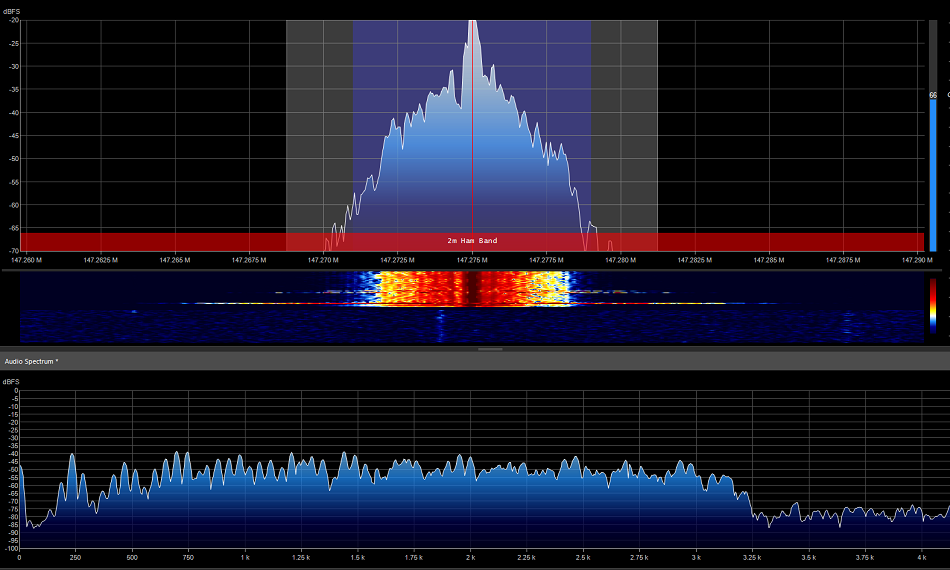
Photo
1
VK6RAV
repeater output audio
without a modulated signal on the system. During daylight hour with
high solar power output the hum from just below 200Hz and related
harmonics across the voice channel.

Photo
2 VK6RAV
repeater output audio
without a modulated signal on the system. During night hour with
obviously no solar power output the hum is not present.

Photo
3 VK6RAV
repeater output audio
without a modulated signal on the system
and the new DC line filter installed.
During daylight hour with high solar power output the hum has been
greatly attenuated and higher harmonic completely eliminated.
With
a somewhat trial-and-error design approach using LTSpice, a final
design came together, and modelling confirmed what appeared to be
suitable attenuation of the embedded tone from the solar charging
regulator’s output supply voltage. The modelling targeted
attenuation at 200 kHz and its related harmonics.
The
C1 capacitor targets high-frequency harmonics, while the rest of the
filter addresses lower frequencies.
The
low-pass filter, designed to remove regulator switching noise from a
14V DC supply with a 4A load, comprises two 1.8mH toroidal inductors
(L1 and L2) in series, wound with 2.9mm² copper (~3m long, DCR
≈ 0.017Ω per inductor), a 1µF non-electrolytic capacitor
(C1) across the input, two paralleled 5600µF electrolytic
capacitors (C2 and C3, totalling 11,200µF) from the L1-L2 junction
to ground, and another pair of 5600µF capacitors (C4 and C5, also
totalling 11,200µF) across the output to ground.
The
switching noise, an unstable 170Hz square wave, includes a
fundamental frequency and numerous harmonics. C1 attenuates
high-frequency harmonics, while the LC stages (L1 with C2/C3 and L2
with C4/C5) form a low-pass filter with a low cut-off frequency. The
total DCR of 0.035Ω causes a 0.14V drop at 4A, delivering
approximately 13.86V—well above the 12V minimum.
Paralleling
the electrolytic capacitors helps reduce ESR, enhancing ripple
suppression and transient response. The filter effectively, though
not perfectly, cleans the noise above 160Hz.

Fig
1 Low Pass Filter Circuit in LTSpice

Fig
2 Low Pass Filter run in LTSpice, set up with a 14v DC voltage
with 1v peak to peak 200Hz square wave embedded. Vn001 (1v peak to
peak square wave), Vn002 (Voltage between L! and L2) and Vn003 (The
much smoother output voltage.

Fig
3 Low Pass Filter modelled to show attenuation by frequency with Elsie filter design application.
The
two inductors are constructed using FT240-43 ferrite cores with 46
turns of 2.9mm² copper automotive cable, producing an inductance of
1.8mH each. The FT240-43 ferrite cores may not be ideal; however,
they were readily available. The inductor value was determined using
a core calculator (toroids.info
FT240-43) and confirmed with a NanoVNA.
The
board layout allows for easy future modifications if performance
needs improvement.

Photo
4 Construction layout
During
daylight hours with high solar power output, the hum has persisted;
however, while still noticeable, it has been greatly attenuated, and
the higher harmonics have been completely eliminated.
There has also been an improvement with the KiwiSDR remote receiver,
with many signal spikes across the spectrum now having disappeared.
Photo
5 VK6RAV
repeater output audio
without a modulated signal on the system
and the new DC line filter installed.
During daylight hour with high solar power output the hum has been
greatly attenuated and higher harmonic completely eliminated.
LTSpice
model file: dc_line_filter_20250331-model01.asc
DC
distribution board wiring details: DC Panel wiring
detail.pdf
TOP
OF PAGE
Page initiated 01 April, 2025
Page
last revised 04 April, 2025
|