|
ALL BAND HF DIPOLE
The All Band HF
Dipole was constructed and refined for use with my Z-Match
Antenna Matching Unit at my previous residence in Melbourne, Victoria
from 2004 - 2007
Despite
the space limitations of a suburban block I wanted an antenna that
would be suitable for all the HF amateur bands, including the so
called WARC bands and ideally including the 160 metre band. The
antenna system should also be useful for other HF services i.e.
broadcast, military etc.
Another aim was to develop an antenna that could
be used portably, that is being able to be simply rolled out and hung
up in a convenient tree or similar.
What became the clear choice was a dipole cut to
no particular frequency, simple cut to the maximum length for the
available space and matched with an AMU (Aerial Matching Unit) to
the transceiver. With the antenna suspended at the centre feed point
to create a low slung inverted vee configuration the antenna is very
easy to install which is consistent with the second aim of
portability. That is the antenna can be suspended from a single
support and is there for easy to erect from a single tree for
example.
I referred to the antenna as a random length
dipole, but there are a couple of limitations to the ultimate dipole
length. First antenna efficiency will drop of significantly at
lengths dramatically less than a half wave length for the lowest
frequency band to be operated. Also it is wise to avoid lengths that
produce extremely high impedance to the AMU as it may be beyond its
ability to match this impedance. The second example is fairly easily
rectified by simple adding or subtracting some length to either the
dipole or the feed line, often as little as a metre will do the
trick.
My final antenna system consisted of a 28 metre
centre fed dipole (14metre for each leg) suspended at the centre and
supported with my existing 6 metre tall galvanised steel pipe mast
fed with 18 metres of 450ohm ladder line via my Z-Match
AMU.
Construction
The physical assembly is
extremely simple and cost effective consisting of standard
electrical copper wire with the insulation removed, light weight end
and centre insulators fashioned from fibre-glass rod. The centre
insulators and support attachment consisting of a heavy duty
stainless steel key ring. See the above photo.
The 18metres of 450ohm
ladder line feed has been installed with sweeping bends and care to
avoid as far as practicable any other cable and metal objects. See
below stand off insulator fashioned from nylon set screw with
fibre-glass spacer sleeve.
One
of the disadvantages of this antenna system is that it is a balanced
system that is each halves of the dipole and feed-line configuration
have to mirror the other. Failure to achieve this will cause the
feed-line to receive and radiate energy which will result in a
distortion of the radiation pattern and also allow the feed-line to
pick up stray signals from computers etc as the feed-line enters the
radio room. Despite this I have found that this antenna system is
reasonably forgiving.

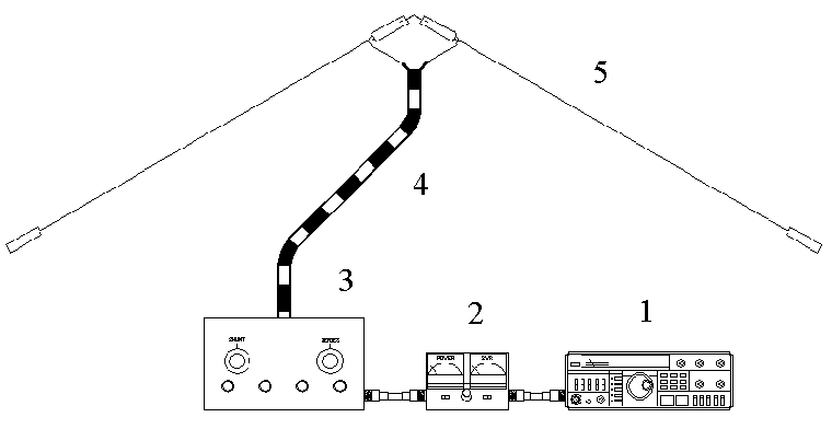
Basic All Band Dipole Arrangement
(1) HF Transceiver.
(2) VSWR Meter.
(3) Z-Match AMU.
(4) 450Ohm Ladder Line. (Can
be any realistic length. In this case it was 18Mtr)
(5) Inverted 'V' Dipole.
(Length subject to available installation space. In this case it was
28Mtr total length)
Performance
The antenna has been
installed roughly in a north-south alignment. When the antenna
configuration is modelled with MMANA-GAL Antenna Analyser, the
following radiation pattern for the 10mtr band is produced. I have
over laid the results on the great circle map centred on Melbourne,
Australia. Now I know this is not to be taken as gospel however it gives some
clues of what is going on and the results have been born out to some
degree by the stations that I have contacted.

The radiation
pattern for this antenna is both and advantage and disadvantage
based on how they form with relation to the various bands. The
10metre band experience seems to be for the most part a good
outcome.
Considering the
above radiation plot for 28.5Mhz with the first 10metre band
contacts on the 8/12/2004 Allan VK4HUX on 28.47Mhz North of
Brisbane, and on the 11/12/2004 David K8CC Missouri USA and Theodore
N6IIU Sonora California USA also on 28.47Mhz.
See below plots
for comparisons with other bands and as I said these results are not
to be taken as gospel, but do give clues about what patterns can be
expected with this sort of antenna system.
The first HF
antenna system that I erected in early 2004 was a simple 40 metre
band dipole in a similar height and alignment. This antenna was
operational on both the 40 metre and the third harmonic band of 15
metres and provided a good operational comparison with the
replacement all band dipole system and gives almost identical
operating characteristics on the two above mentioned bands.
The random
length all band dipole represents some clear advantages in cost and
operational flexibility within the limitations of the average
Australian suburban block. There for if you can have only one HF
antenna the random length all band dipole would be a pretty good
choice.


The
very
interesting 3 D radiation plot of the antenna
at 28.50MHz.
References
The
ARRL Antenna Book.
The
1990 ARRL Hand Book.
TOP
OF PAGE
Page
last revised 12 March 2022
|