|
435MHz
5 PETAL CLOVER LEAF ANTENNA
435MHz
5 Petal Cloverleaf tower mounted antenna. November 2016
In need of a horizontally polarized 70cm band antenna for SSB (Single Side Band) work, as well as a horizontally polarized omnidirectional
(HPOD) antenna for both the 2-meter band and 70-centimeter band at a proposed beacon site, I concluded that constructing a robust and easily replicable unit, requiring minimal maintenance, would be ideal. After careful consideration, I opted for a 5 Petal Cloverleaf antenna, sometimes referred to as a Big Wheeled antenna.
Construction:
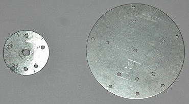
The antenna's design centres around a standard male N connector, with a 100mm diameter
aluminium radial mounting disk featuring a 15mm centre hole for attachment to the N connector using the standard coax gland screw cap, as depicted in Figure 4 and Photos 3 to 10. The elements are affixed to the mounting disks using 3mm diameter pop-rivets.
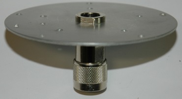
The smaller upper disk is connected to the coax centre pin of a standard male N connector and securely positioned within the N connector using two-part epoxy. To ensure water resistance, a small rubber grommet has been custom-fitted at the end of the N connector body, with a layer of marine-grade silicone applied.
The antenna is mounted using a standard antenna mirror mount bracket, fitted with a female-to-female N connector bulkhead socket, accommodating various similar antennas constructed around male N connectors.
See:
Generic Antenna Mount.
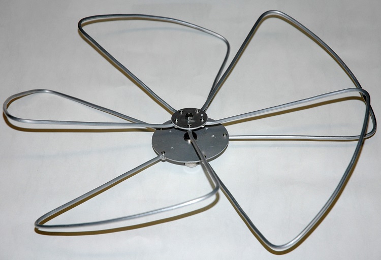
Photo 1 435MHz
5 Petal Cloverleaf assembled shown
from above.

Photo 2 435MHz
5 Petal Cloverleaf assembled shown
from below.

Figure 1 5
Petal Cloverleaf
general layout.

Figure 2 Cloverleaf element dimensions.
| SECTIONS |
FREQUENCY
MHz |
| 144.5 |
145.5 |
146.5 |
222 |
430 |
435 |
440 |
| mm |
mm |
mm |
mm |
mm |
mm |
mm |
| RAD
A |
701 |
696 |
691 |
459 |
241 |
239 |
236 |
| RAD
B |
59 |
58 |
58 |
39 |
20 |
20 |
20 |
| LGTH
C |
651 |
646 |
642 |
426 |
224 |
222 |
220 |
| LGTH
D |
625 |
620 |
616 |
409 |
215 |
213 |
210 |
| LGTH
E |
6 |
6 |
6 |
6 |
6 |
6 |
6 |
| LGTH
F |
20 |
20 |
20 |
20 |
20 |
20 |
20 |
| TOTAL
LENGTH |
2102 |
2088 |
2074 |
1377 |
724 |
716 |
708 |
| TOTAL
SECTION LENGTH |
2076 |
2062 |
2048 |
1351 |
698 |
690 |
682 |
Figure 3 Cloverleaf element dimensions table.

Figure 4 Cloverleaf
antenna hub plates dimensions.

Figure 5 Cloverleaf hub
assembly with element attachment.
Adjusting the
distance D1 with the top plate and stud screw was use to adjust for
the lowest SWR.
 |
 |
| Photo 3
5
Petal Cloverleaf hub plates.
|
Photo 4
5
Petal Cloverleaf lower hub plate
assembled.
|
 |
 |
| Photo 5
5
Petal Cloverleaf lower hub plate
assembled.
|
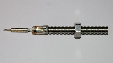
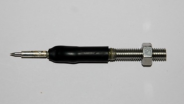
Photo 6
Threaded stud mated with N Connector pin.
|
 |
 |
| Photo 7
Threaded stud mated with N Connector pin including heat-shrink
tube. |
Photo 8
435MHz
5
Petal Cloverleaf
hub and stud assembled. |

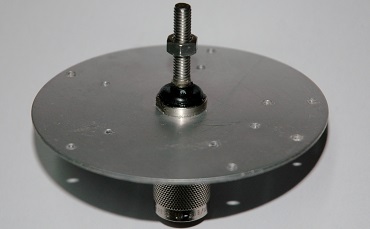
Photo
9
435MHz
5
Petal Cloverleaf
antenna hub complete assembled.
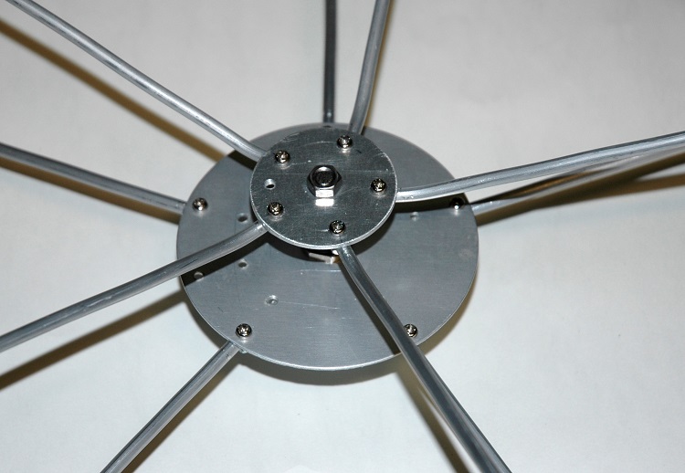
Photo
10
435MHz
5
Petal Cloverleaf
antenna hub complete assembled with elements attached.
Antenna
testing
With the antenna assembled on a conveniently accessible test mast, positioned well above the ground and clear of any surrounding metallic objects, it was connected to an AIM UHF antenna
analyser to assess its performance.
The objective here was to achieve the lowest SWR (Standing Wave Ratio) for the operating frequency of 435MHz, with the resonant frequency ideally as close as possible to this value.
The AIM UHF antenna analyser provides a comprehensive display of all relevant data and, importantly, allows the analysis to be projected to the antenna end of the coaxial cable, providing a more accurate representation of the antenna's characteristics.
By making modest adjustments, an SWR of 1.24 was achieved at 435MHz, with the resonant frequency measured at 453MHz. The SWR remained consistently low across the entire 70cm band, with a maximum of 1.5 observed at the band edges (420 - 450MHz). The phase angle, depicted in purple, exhibited a shallow zero-angle crossing at 453MHz, indicating the resonant frequency of the antenna.

Figure 7 435MHz
5 Petal Cloverleaf AIM
UHF antenna analyser plot.
.
AIM
UHF antenna analyser explanation;
| SWR |
Standing
Wave Ratio. |
| Zmag |
Total
Impedance. |
| Phase |
Phase
angle between voltage and current. |
OMNIDIRECTIONAL
HORIZONTALLY POLARIZED UHF ANTENNA DESIGN, Project Number:
<PH-GSI-0701>
UHFOmniDesignMQP.pdf
TOP
OF PAGE
Page initiated November, 2016
Page
last revised 27 January, 2026
|