Peter Miles
Northam, Western Australia QRZ Page: VK6YSF
Email
Social
Media
Buy me a coffee
If you found information on this site interesting, beneficial, or learned something new, please consider buying me a cup of coffee by clicking the coffee cup below.
It helps keep the website going and is greatly appreciated.
YAMAHA RX-V550 TUNER-AMPLIFIER REPAIR
Yamaha
RX-V550 tuner-amplifier repair. 29 October 2019.
There’s
something deeply satisfying about rescuing a well-built piece of
audio gear from silence. The Yamaha RX-V550 is one of those solid
mid-2000s home theatre receivers that, when working, delivers great
sound and reliability. But when this one landed on the bench, it was
stone dead.
With
no obvious signs of damage, blown fuses, no scorched marks or any bulging capacitors. Probing through the power board quickly showed
there was no standby voltage. The main transformer was fine however
the control circuits were getting no power. Somewhere between the
mains input and the standby rail.
After
researching common faults online, I learned that in the power supply
section, the C405 capacitor - a 22 nF, 630 V polyester type is often
the main culprit. I replaced it, and the receiver now powers on
briefly: the display lights up for about two or three seconds before
shutting down again.
This
capacitor is part of the mains-sampling network, which helps the
circuit detect when the incoming power is present and within
specification. Over time, the original capacitor had drifted well
out of tolerance, preventing the circuit from correctly sensing the
AC mains. As a result, the receiver stayed in a permanent “off”
state - a well-known issue with this particular model.
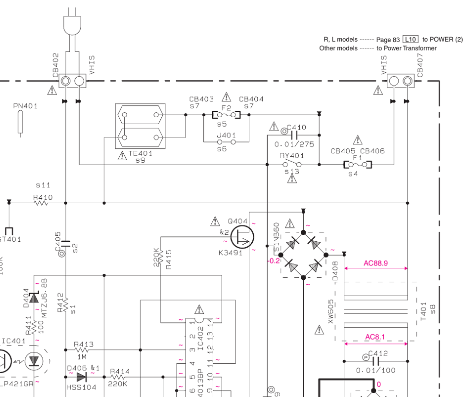
Figure
1. Circuit schematic 230VAC supply arrangement including the
C405 22nF, 630V polyester capacitor
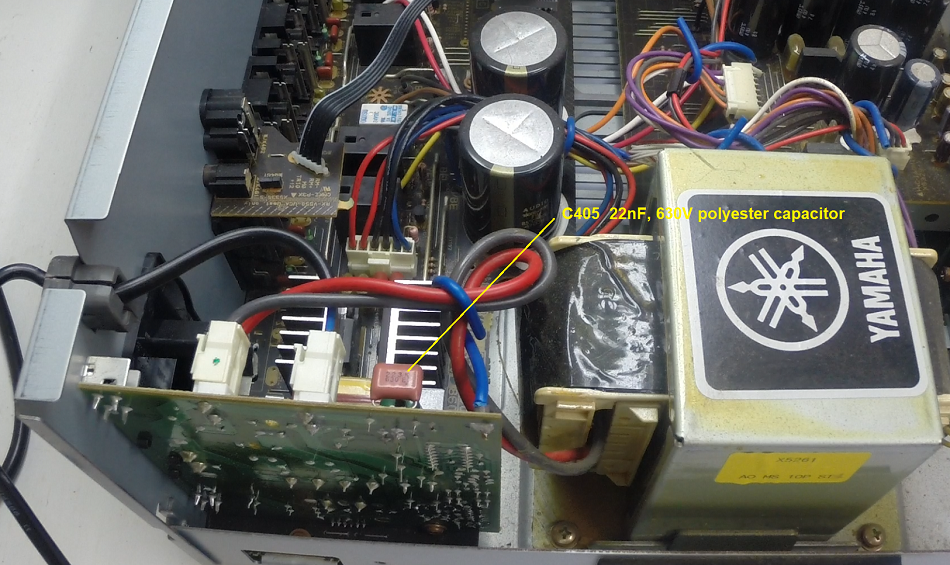
Photo
1. Location of the C405 22 nF, 630 V polyester capacitor
A
divide-and-conquer approach was used to isolate the fault. First,
both the left and right main amplifier channels were disconnected,
and the receiver was powered on. This time, the main display stayed
on, suggesting the problem was likely in one of the amplifier
channels.
Next,
each channel was tested individually by disconnecting one while
leaving the other connected. In both cases, however, the amplifier
remained on, regardless of whether the left or right channel was
connected.
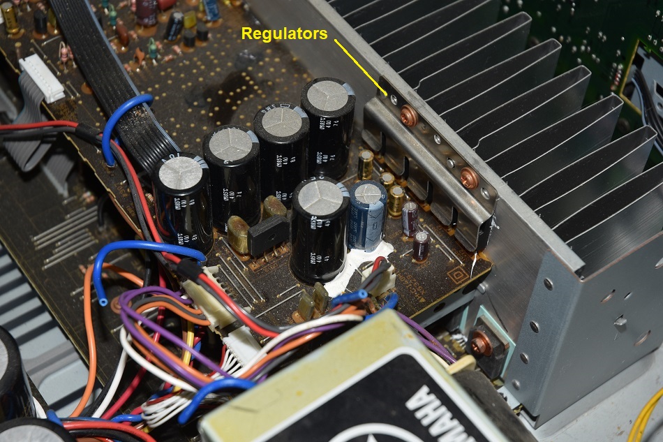
While
probing the main amplifier board, I noticed unusual voltages around
the power supply regulators. This drew my attention to the group of
five voltage regulators. Each regulator was removed and tested
individually, and for reasons I don’t fully understand three of
them were found to be faulty.
All
the faulty regulators were replaced and after the replacements, the
amplifier powered up without any issues. Once connected to speakers
and a signal source, it operated perfectly.
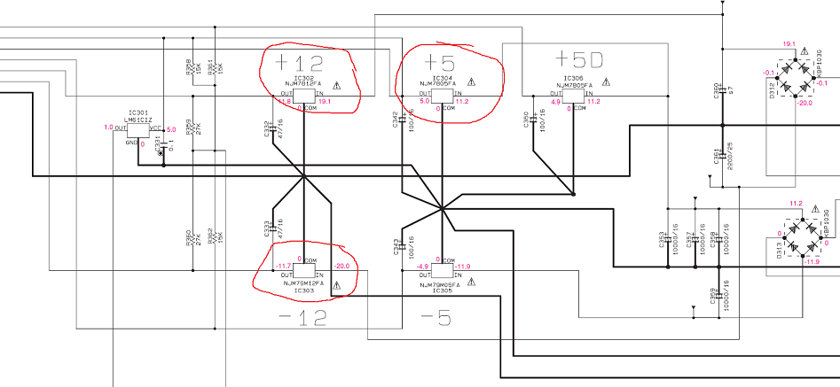
Figure
2. Circuit schematic of the main amplifier power supply
regulators.
Photo
2.Main amplifier power supply regulators mounted to
the heatsink.
The
below components were identified as faulty and were replaced.
C405
22 nF, 630V polyester type capacitor
IC104
+12V regulator had failed producing a 1.2V output.
IC302
-12V regulator had failed producing a 0.5V output.
IC303
+5V regulator had failed producing a 1.1V output.