|
DUAL BAND DIPOLE - 40 AND 15 METRE BANDS
Dual
band dipole for 40m (7 - 7.3 MHz) and 15m (21 - 21.45MHz) bands at my previous residence in Melbourne, Victoria
in 2004
For my first HF antenna I selection a
basic 40m band dipole primarily as a simple antenna that provided
access to one the most versatile amateur HF bands. All basic 40m
dipole antennas have a significant potential second advantage that
of having a direct third harmonic relationship with the amateur 15m
band allowing the antenna to load reasonably well on 15m as well as
the 40m band.

Figure
1 Typical HF
dipole configuration complete with 1:1 balun and 50ohm coax cable to
transceiver.
Description
Half wave length
of copper wire, fed at the centre with a 1:1 balun and coax
cable to the transceiver. This antenna configuration when cut to
suit the 40m band will provide an approximate 50 ohm feed point
impedance for both the 40m band and the third harmonic band of 15m
and may not require an ATU for most of the coverage of these two
bands.
The 1:1 Balun, shown in the drawing, is
to transform the balanced dipole to an un-balanced coax transmission line.
The
lengths of the 40m dipole and other amateur band frequencies are
presented in the Table 1 and have been determined by the below
formula 
Frequency
in MHz, K = K factor refered to in the below chart.
The dipole is and
electrical half wavelength not a physical length with the electrical
length being slightly shorter. The basic wavelength calculation is
multiplied by a factor of ‘K’. Typically K is a value between
0.96 and 098 and is mainly dependant on the ratio of the wavelength
and the diameter of the wire used. The K factor can be derived from
the below Figure
2 Chart

Figure
2 'K'
Factor chart that determines the element multiplier factor based on
the ratio of the diameter of the conductor diameter to a half wave
length.
Using these
formulae it is possible to calculate the length of a half wave
dipole. Even though calculated lengths are normally quite repeatable
it is always best to make any prototype antenna slightly longer than
the calculations might indicate as it is better to make the dipole
slightly too long than too short so that it can be trimmed to
achieve the best possible match on both bands.
|
Band
|
Centre
Frequency
|
Length
'A' (Mtr)
|
Length
'A' (inches)
|
|
160
|
1.84
|
79.89
|
3145.32
|
|
80
|
3.6
|
40.83
|
1607.61
|
|
75
|
3.9
|
37.69
|
1483.94
|
|
60
|
5.3
|
27.74
|
1091.96
|
|
40
|
7.05
|
20.85
|
820.91
|
|
30
|
10.12
|
14.53
|
571.88
|
|
20
|
14.15
|
10.39
|
409.00
|
|
17
|
18.1
|
8.12
|
319.74
|
|
15
|
21.2
|
6.93
|
272.99
|
|
12
|
24.95
|
5.89
|
231.96
|
|
10
|
25.5
|
5.76
|
226.96
|
|
6
|
52
|
2.83
|
111.30
|
Figure
3 'K'
Table of dipole lengths 'A' for various armature bands

Figure 4
Produced with data generated from 4NEC2 antenna
modelling software. Clearly shows the ideal SWR dips at the lower
edge of the 40m band and upper middle of the 15m band.
The 4NEC2
antenna model indicated that the minimum SWR on the 15m band is
higher than that on the 40m band and that the 15m SWR dip is higher
frequency than would be expected if the dip was absolutely third
harmonically related. In my particular experience of the real
antenna it was found that both the 40m and 15m bands offer practical
access to both bands, however it is likely that the real world
result will vary from installation to installation.

Figure
5 Radiation
plot for the 40m band were produced using NEC based antenna modeller and optimizer
4NEC2.

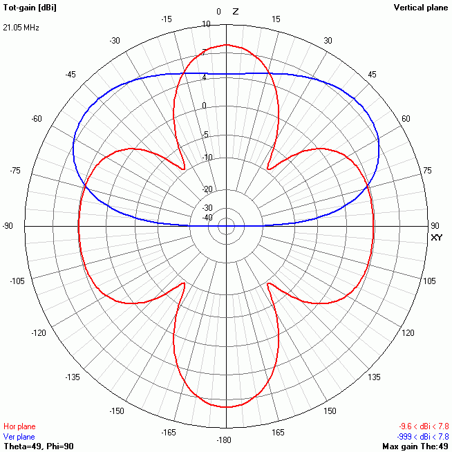
Figure
6 Radiation
plot for the 15m band were produced using NEC based antenna modeller and optimizer
4NEC2.
Construction
The physical assembly is
extremely simple and cost effective consisting of standard
electrical copper wire with the insulation removed, light weight end
and centre insulators fashioned from fibre-glass rod. The centre
insulators and support attachment consisting of a heavy duty
stainless steel key ring. See the below photo.

Photo 1
Inverted 'V' Dipole and 1:1 balun assembly.
References
The
ARRL Antenna Book.
TOP
OF PAGE
Page
last revised 12 March 2022
|