|
ALL BAND DIPOLE Mk2
Improved
All Band HF Doublet was constructed and refined from the experience
from my previous All Band HF Doublet for use with a Z-Match Antenna
Matching Unit. 2011
| With
a 1064m2 (1/4 acre) town block with a depth of 60mtr (200') I
intended to improve on my previous All Band HF Doublet with an
antenna that would be suitable for all the HF amateur bands,
including the so called WARC bands and including the 160 metre band.
The antenna system should also be useful for other HF services i.e.
broadcast, military etc. With a newly installed mast positioned to
achieve an Inverted 'V' of 42mtr in length and achieving an apex
of 11mtr above ground the new All Band HF Doublet should experience
significant performance improvements, particularly on the lower
bands. I had seriously considered constructing something different
as the All Band HF Doublet had be done and there many alternatives,
but the flexibility that this configuration offers for the
simplicity of construction I ultimately decided to go with what I
had learnt and go with a proven performer.
Description
The
All Band HF Doublet is often referred to as a random length dipole
as it is generally as long as the available space within reason, but
there are a couple of limitations to the ultimate dipole length.
First antenna efficiency will begin to drop off at dipole lengths significantly
less than a half wave length for the lowest frequency
band to be operated. It is also wise to avoid lengths that produce
extremely high impedance to the Matching Unit as it may be beyond
its ability to match this impedance. The second example is fairly
easily rectified by simple adding or subtracting some length to
either the dipole or the feed line, often as little as a metre will
do the trick. While the antenna is well less than a half wave length
at 1.8 MHz, at just over a quarter wave length it will still give
usable access to this band.
|
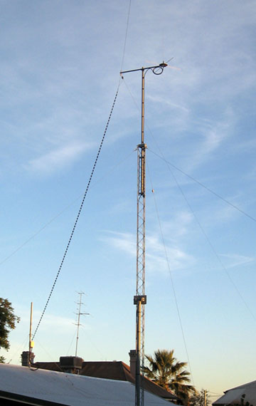
Photo 1
All Band HF Doublet
|
The
completed antenna system consists of a 42 metre centre fed doublet
(21 metres for each leg) suspended at the centre and supported by
the short 1 metre crossarm attached
at the top of a 11mtr tower. The doublet is fed with 8mtrs of 450ohm
ladder line that is then connected to a 3.5mtr section of twin
heliax (Explained in detail below) that is run into the shack to a Z-Match
antenna matching unit.
The
ARRL handbook presents the results of a comparative study of the All
Band HF Doublet constructed as a flat top doublet and as an inverted
'V' configuration. Conclusion was that both configurations offer
a practical and flexible antenna with the flat top representing a
superior low angle radiation pattern due to its general greater
height above ground.
One
of the disadvantages of this antenna system is that it is a balanced
system that is each halves of the doublet and feed-line
configuration have to mirror the other. Failure to achieve this will
cause the feed-line to receive and radiate energy which will result
in a distortion of the radiation pattern and also allow the
feed-line to pick up stray signals from computers etc as the
feed-line enters the radio room. Despite this I have found that this
antenna system is reasonably forgiving.
Features
While the antenna was
principally the same as the previous All Band HF Doublet there was a
key new design challenge which was how access the balanced ladder
line to the radio room located within a steel clad building. Ladder
line is a very efficient transmission line particularly when high
SWR is likely as in the proposed configuration; however the ladder
line must be kept well clear of any metal structures and prefers to
be run in a sweeping manner avoiding sharp bends. The solution was
to terminate the twin ladder line conductors into a twin section of
coax cable for the run into the shack. With the shields bonded
together at both end of the twin coax section producing a section of
shielded balanced 100ohm transmission line. The use of coax in this
way can introduce high
losses when operated at high SWR particularly on the higher HF
bands, it is therefore important to use the best, lowest loss coax
available and keep to section as sort as is possible. I chose to use
1/2" heliax that was available as the run would be about 3.5mtr in
length. While not important that the coax or heliax follow the same
route it is critically important that they be of the same length and
the shields be bonded at both ends and earthed ideally at both ends,
but at least at the station end.
Construction
The
inverted 'V' doublet was constructed using 42mtr of standard
2.5mm2, 7 strand copper earth wire with the PVC insulation removed
and glazed porcelain electric fence insulators at the end and 'V' apex attachments. The apex of the
'V' was attached to a
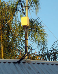
small steel cross-arm located at the top of the 11m tower, fed with
8mtrs of 450ohm ladder line dropped vertically away from the 'V'
apex to a small plastic junction box attached at a small sub mast
located in the centre of radio room building's steel roof.
The ladder line that is then connected to a 3.5mtr section of
twin heliax at the junction box where the shields of the twin heliax
are bonded and grounded to the small sub mast, which is electrically
bonded to the steel roof. The twin heliax is then routed through the
roof space and wall cavities and presented via two SO259 bulkhead
sockets where the shields of the twin heliax are also bonded and
grounded to the station earth.
The
feed-line is then match via a balance matching unit such at the
Z-Match antenna matching unit to the typical 50ohm radio antenna
socket. It is obviously critically important that the SWR is
carefully monitored during the match procedure.

Figure
1 General Layout.
Basic
All Band Dipole Arrangement
(1)
Inverted 'V' Dipole. (Length subject to available installation
space. In this case it was 42Mtr total length)
(2)
450 Ohm Ladder Line. (Can be any
realistic length. In this case it was 7.5Mtr)
(3)
Junction box (Ladder line - twin heliax
interface)
(4)
Twin heliax
(As short as possible.
In this case it was 3.5Mtr)
(5)
Twin
SO259 bulkhead sockets
(6)
Z-Match AMU. See
Z-Match AMU
(7)
VSWR Meter.
(8)
HF Transceiver.
|
|
|

|
|
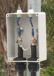
Photo
2 Junction box (Ladder line - twin heliax interface) |
Photo
3 Junction box (Ladder line - twin heliax interface)
assembly |
Photo
4 Twin
SO259 bulkhead sockets |
Operational
It
is critically important that the SWR is carefully monitored during
the match procedure required after band changes and when even
moderate changes in frequency are made within a band. This is
particularly important on the lower frequency bands including the 20
and 30mtr bands for significant moves and for even minor frequency
moves on the 80 and 160mtr bands.
See the
AIM 4170C antenna analyser displays for
the 160, 80,40 and 30metre bands
in Fig#2 - 5 below. Note
the very narrow band width of 6kHz below a SWR of 1.5
- 1 for the 160m band
The
Z-Match antenna matching unit while not exclusively designed for a
balanced antenna system is particularly well suited to this
configuration. A balanced antenna system requires that each half of
the doublet as well as each side of the transmission line be a near
mirror image and should also avoid nearby trees and structures in
particular metallic structures. When the system is balanced the
transmission line will have equal, but opposite current flowing in
each line. This will cancel out any radiation or reception on the
transmission line.
The
transmission line is the main reason for maintaining a well balanced
system as it will be prone to radiating and receiving signals as it
enters the radio room. Devices such as computers radiate noise which
may find its way into the sensitive radio receiver and strong fields
around un-balanced transmission feed may interfere with other
sensitive equipment.
A
real world issue for many if not most balanced antenna systems is
achieving this more or less perfect balance. Imbalance is primarily
caused by more capacitive coupling to one side of the system than
the other. Lloyd Butler suggests a method to counter this effect by
simply adding additional capacitance to the opposite side the
system. There for I have added this feature to my version of the
Z-Match. Which side requires the additional capacitance is a bit of
trial and error, but a method to test for balance is to measure the
current in each leg simultaneously and observe if they are equal or
to simply adjust until locally generated noise reduces. The further
the problem noise source is from the antenna system the more likely
it will be the antenna and not the transmission line that is
receiving it and the less effective the balance capacitor will be.
Anecdotally the All Band HF
Doublet is performing well on all bands from 80 to 10m and as well
could be expected given its length on 160m. From
Northam
,
Western Australia
consistently reasonable contacts have been established with the
Australian east coast and
New Zealand
via the 80m band. All bands from 40m and above have usable world
wide coverage subject to conditions.
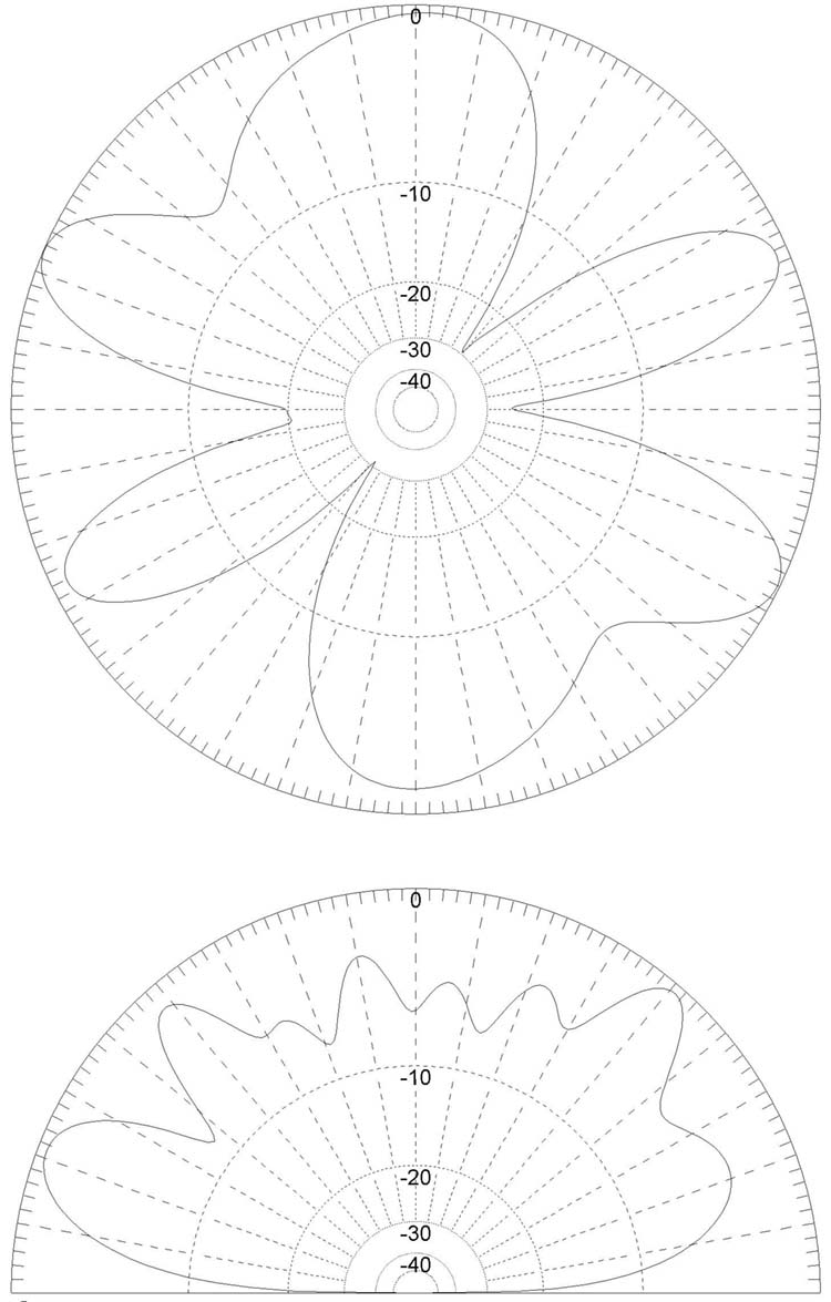
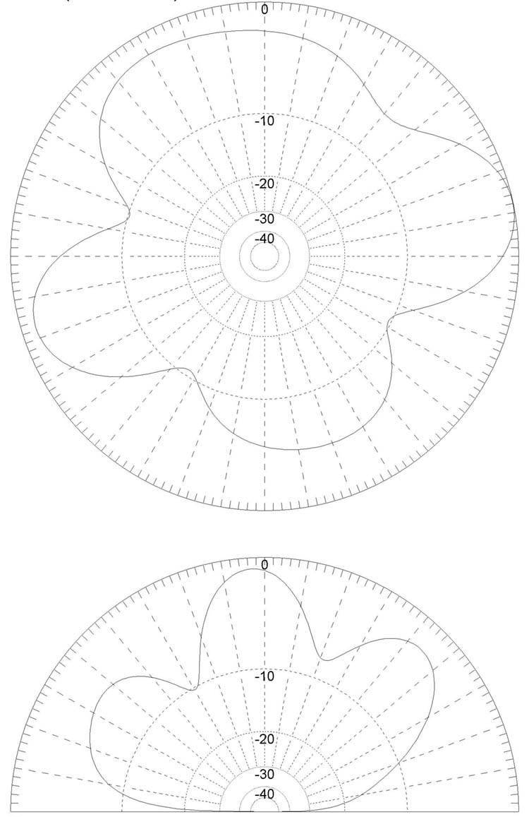
See
below MMANA-GAL antenna analyser
modelled radiation plots for 30,
20, 17, 15, 12 and 10m bands. AIM 4170C antenna analyser displays
for the 160, 80,40 and 30m bands
|
|
|
Figure
2 AIM 4170C antenna analyser display
of the antenna system including the Z-Match at 1.85MHz. Note
the very narrow band width of 6kHz below a SWR of 1.5
- 1
|
|

|
|
Figure 3 AIM 4170C antenna analyser display
of the antenna system including the Z-Match at 3.6MHz. Note
the band width of 25kHz below a SWR of 1.5
- 1
|
|
|
|
Figure 4 AIM 4170C antenna analyser display
of the antenna system including the Z-Match at 7.13MHz. Note
the band width of 70kHz below a SWR of 1.5
- 1
|
|

|
|
Figure 5 AIM
4170C antenna analyser display of the antenna system including
the Z-Match at 10.125MHz. Note the band width of 150kHz (Full
30m band) below a SWR of 1.5 - 1
|
MMANA-GAL
antenna analyser
modelled radiation plot for 30,
20, 17, 15, 12 and 10m bands.
|
|

|
|
Figure 6 Modelled radiation plot for the 10m band
|
Figure
7 Modelled radiation plot for the 12m band
|
|

|

|
|
Figure 8
Modelled radiation plot for the 15m band
|
Figure 9
Modelled radiation plot for the 17m band
|
|

|
|
|
Figure 10
Modelled radiation plot for the 20m band |
Figure 11
Modelled radiation plot for the 30m band |
Summary
The random length all
band doublet represents some clear advantages in cost and
operational flexibility within the limitations of the average
Australian suburban block. There for if you can have only one HF
antenna the random length all band doublet would be a pretty good
choice.
References
WIRE
SPLICE - INLINE
Wire splicing for inline joining of aerial
wire.
WIRE
SPLICE TERMINATION
Wire splicing for terminating an antenna
aerial wire or guy wire to a strain insulator or thimble.
WIRE
SPLICE TERMINATION & TAIL
Wire splicing for terminating an antenna
aerial wire to a strain insulator with a tail for connecting to the
feed line.
The
ARRL Antenna Book.
The
1990 ARRL Hand Book.
The
above radiation plots were produced using MMANA-GAL Antenna Analyser
software by JE3HHT, Makoto (Mako) Mori at http://hamsoft.ca/
TOP
OF PAGE
Page
last revised 12 March 2022
|