|
RADIO TOWER
Radio Tower Design and
Construction 2010
 The
radio mast, an almost fundamental component of any amateur radio
station was in my case a compromise of a number of mental design
aspirations and by the opportunity of the available hardware that
could be acquired and fabricated. The amateur radio station's
collection of antennas is for me a dynamic thing that will change and
evolve over time, however if the mast is well designed it should
require little modification. The
radio mast, an almost fundamental component of any amateur radio
station was in my case a compromise of a number of mental design
aspirations and by the opportunity of the available hardware that
could be acquired and fabricated. The amateur radio station's
collection of antennas is for me a dynamic thing that will change and
evolve over time, however if the mast is well designed it should
require little modification.
My
first purchased was a 7.7mtr section of lattice tower advertised on
VKHam. I had transported the tower to my home without having fully
determined how it would fit with my plans. I had however formed a
bit of plan that the mast could be a tilt over structure based on
photos that I had seen on the internet without any detail of how
these masts had been constructed.
I
contacted local ham Jim VK6CA for his thoughts on what was possible,
Jim clearly saw the vision of what was needed to be done based
several successful and less successful designs of this type that had
been developed by him and others.
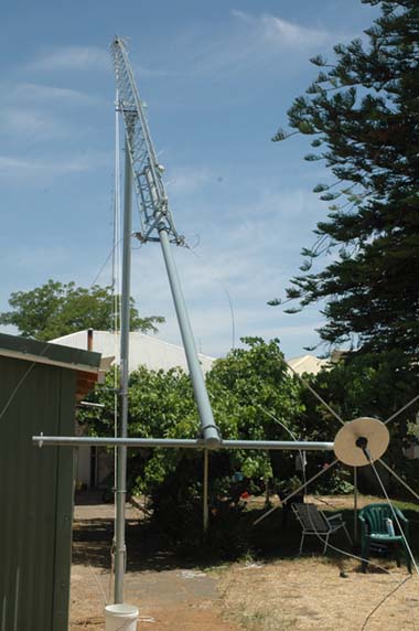
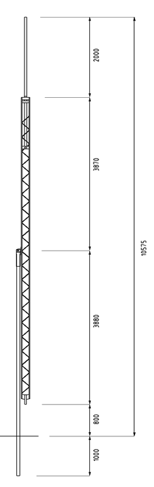
The
final design was for an over all mast/tower consisted of a 5.6mtr
length of 80mm medium duty galvanized steel tube concreted 1mtr into
the ground with a fabricated cradle assembles fitted to the top. The
lattice tower would have a fabricated steel bracket complete with a
pivot rod attached just above centre height of the lattice tower,
about the centre of gravity of the lattice tower. The rod bracket
would sit in the cradle assembly held in place by the weight of the
tower.
The
top of structure would now have a total height above ground of
8.3metres. Finally there wound be an addition 2.0mtr section of 40mm
diameter galvanized steel tube attached to the top of the mast,
achieving total structure height above ground of 10.3mtr.
The
mast is stabilized against high wind loading with three guy wires
positioned approximately 120deg from each other. It is intended that
at least one of the guy wires will be used as a multi-band radiator
covering bands between 7 and 29 MHz.
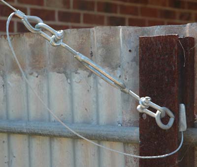
Swage
connectors were used as part of the termination
of the guy wires, these connectors allow the wires to be bridged
from the mechanical termination and bonded to the mast for example.
The 3mm swage connector is
marine grade attachment for small size wire rope from Zenith, Cat
WSS203; a malleable elongated plated copper sleeve that produces a
neat, quality electrical connection with an acceptably strong
physical connection. The swage connector in conjunction with
galvanised wire rope thimbles, D shackles and adjustable turn
buckles creates an effective and adjustable guy wire attachments.
Although
the use of rope thimbles, D
shackles and adjustable turn buckles intentionally allows for some
mechanical movement the connection between these fittings is not an
ideal electrical connection and run the risk of creating electrical
noise as the fittings move due to wind for example. The solution is
to electrically bond across these mechanical connections by
installing a conducting lead from the guy wire to the metal mast for
example.
See photo#3
Operationally
there is no need to climb the tower to carry out work on the
antennas. By disconnecting one of the guy wires and un-bolting the
tower attachment near the base of the structure the lattice tower
which is slightly top heavy can managed easily with ropes and tilts
over. The process is a relatively simple one person operation as is
reinstating the mast to the up right position.
While
I quite like climbing radio towers it is clearly safer and easier to
carry out antenna work from the ground. The completion this project
is not the end; it is the beginning of the real projects.
References
WIRE
SPLICE TERMINATION
Wire splicing for terminating an antenna
aerial wire or guy wire to a strain insulator or thimble.
ARRL
Antenna Hand Book
Links
For key issues to be considered in tower design and maintenance - See:
The
Ten Most Common Tower Building Mistakes
http://www.championradio.com/common.tower.building.mistakes.html
For more information on tower and station earthing - See:
Grounding Systems for Amateur Radio Stations
http://www.ve3sqb.com/hamaerials/kf6gdj/
For more information on
Galvanic corrosion - See:
http://en.wikipedia.org/wiki/Galvanic_corrosion
TOP
OF PAGE
Page
last revised 12 March 2022
|