|
DUAL BAND J-POLE ANTENNA
The Dual Band
J-pole antenna (6Mtr
and 2Mtr bands) constructed
and used at my previous residence in Melbourne, Victoria
from 2001 - 2007
Considering the limited space available and the objective of minimizing visual clutter caused by multiple antennas, the need arose for antennas capable of covering multiple bands. After contemplating various options, the idea of utilizing a dual-band J pole antenna emerged as a viable solution. The simplicity of the J pole design and its ground independence, which eliminates the need for ground plane radials, made it an appealing choice.
The intended antenna design would provide coverage across the entire 6-meter band (50 - 54MHz) and the entire 2-meter band (144 - 148MHz), with a slight bias towards the upper halves of both bands.
The J pole antenna consists of a vertical element measuring half the wavelength, accompanied by a folded quarter-wave match stub. It's important to note that the stub itself does not transmit or receive any energy; rather, it acts as an impedance transformer, allowing the desired feed impedance to be extracted.
By employing this design, the objective is to achieve a compact, efficient, and multi-band antenna system while maintaining an aesthetically pleasing appearance and minimizing the impact on the surrounding environment.
|

|

|
|
FIG 1
|
|
Practical
construction
The primary component of the antenna is a 5-meter long
aluminium tube with a diameter of 30mm.
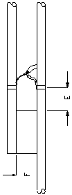
For the 6-meter band, the calculated stub length for a frequency of 52.5MHz is 30 x 1520mm, including 150mm for mounting. The stub is positioned 4090mm from the top of the main element to the top of the stub mounting plate. The mounting plate for the 6-meter band stub measures 150 x 75mm.
The 2-meter band, the calculated stub length for a frequency of 146.5MHz is 16 x 583mm, including 100mm for mounting. The stub is mounted 1448mm below the top of the main element, up to the top of the mounting plate for the 2-meter band stub, which measures 100 x 30mm.
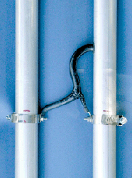
To attach the 6-meter and 2-meter band stubs, a fabricated mounting plate is used along with stainless steel hose clamps. This approach offers several advantages, including no need to drill holes in the main elements, ensuring the structural integrity of the antenna. It also allows for infinite adjustment opportunities and facilitates easier recycling of the antenna for future projects. Additionally, the installation appears neat and robust.
The RG213 coaxial cable is routed inside the main element and exits above the feed point connection. It is essential to protect the coaxial cable by using rubber grommets at the points where it exits the tube.
DIAGRAM
OF THE DUAL BAND J-POLE
| Frequency:
|
50 - 54Mhz
and 144 - 148Mhz
|
| Polarisation: |
Vertical |
| (A)
Main 6M element: |
4090mm + mounting material |
| (B)
6M
stub: |
1370mm
+ mounting material |
| (C)
Main 2M element: |
1448mm |
| (D)
2M
stub: |
483mm
+ mounting material |
| (E)
Feed point for 6M: |
Approximately 90mm.
Subject to adjustment for lowest VSWR
|
| (F)
6M stub spacing: |
75mm |
| (G)
Feed point for 2M: |
Approximately 40mm.
Subject to adjustment
for lowest VSWR
|
| (H)
2M stub spacing: |
30mm |
The
dimension of the J pole may also be arrived at by using the below formula:
| Length
(Mtr) :
|
300/f x k x el + mounting sectio
|
| f
:
|
Operating frequency e.g. 52.5MHz
|
| k
: |
The effect of the diameter of the material in relation to
the wave
length (0.955)
|
| el
: |
Chosen
element e.g. 3/4 wave length main element,
1/2 wave tuning
stubs or 1/4 wave matching stubs, 0.75, 0.50 Or 0.25 respectively.
|
| mounting
section
: |
The amount of extra physical material required for mounting. |
|
|
|
| FIG 2 |
FIG 3 |
|

|

|
|
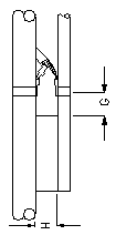
| The
6Mtr band stub mounting plate. |
The
6Mtr band stub mounting plate assembly. As in FIG 2 |
The
2Mtr band stub mounting plate assembly and coax feed through
and connection. As in FIG 3 |
The simple J pole antenna is capable of excellent results as the below
antenna computer modelling of a 2M band J pole antenna illustrates.
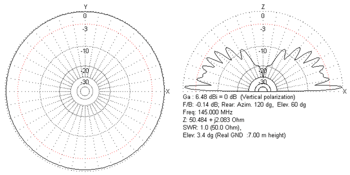

The above
radiation plots were produced using MMANA
Antenna Analyser software by JE3HHT, Makoto (Mako) Mori.
References
The
ARRL Antenna Book.
The
1990 ARRL Hand Book.
For more information on the
J-Pole see: http://en.wikipedia.org/wiki/J-pole
TOP
OF PAGE
Page
last revised 12 March 2022
|