|
BROADBAND HF TRAVELLING
WAVE DIPOLE
Broadband
HF Travelling Wave Dipole (2 - 30MHz) Version#2. October 2016
With
the view to establish a quick and easy multi-band antenna deployment
for portable and camping operations a travelling Wave Antenna with and
9:1 voltage
balun is one possible solution.
Description
A dipole can be modified by inserting resistive loading networks so as to produce standing waves between the
feed point and the networks. With the suitable voltage balun the
resistive network values dipole sections can be adjusted to developed a travelling wave dipole whose VSWR is less than 2:1 from 3 to 15 MHz and does not exceed 2.6 to 1 from 2.3
to at least 30 MHz.

Figure 1 Broadband
HF Travelling Wave Dipole
Construction
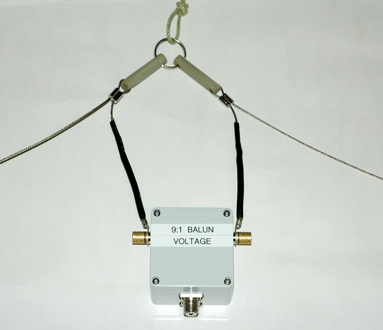
The physical assembly is
extremely simple and cost effective consisting of stranded stainless
steel wire, light weight end
and centre insulators fashioned from fibre-glass rod. The centre
insulators and support attachment consisting of a heavy duty
stainless steel key ring. See the below photo 1. This arrangement
was chosen so that alternative baluns can be easily swapped in and
out.

Photo 1
Broadband
HF Travelling Wave Dipole apex and feed point assembly including bulun.

Figure 7 Broadband
HF Travelling Wave Dipole (1 - 60MHz). AIM
4170C antenna analyser plot.
AIM
4170C antenna analyser explanation
|
SWR
|
Standing
Wave Ratio.
|
|
Zmag
|
Total
Impedance.
|
|
Phase
|
Phase
angle between voltage and current.
|

Figure
8
Broadband
HF Travelling Wave Dipole radiation plot at 3.650MHz. MMANA Antenna
modelling.

Figure
9
Broadband
HF Travelling Wave Dipole radiation plot at 5.30MHz. MMANA Antenna
modelling.

Figure
10
Broadband HF Travelling Wave Dipole radiation plot at 7.150MHz. MMANA Antenna modelling.

Figure
11
Broadband HF Travelling Wave Dipole radiation plot at 10.120MHz. MMANA Antenna modelling.

Figure
12
Broadband
HF Travelling Wave Dipole radiation plot at 14.150MHz. MMANA
Antenna modelling.

Figure
13
Broadband
HF Travelling Wave Dipole radiation plot at 21.2000MHz. MMANA
Antenna modelling.

Figure
14
Broadband
HF Travelling Wave Dipole radiation plot at 28.500MHz. MMANA
Antenna modelling.
Details
of the
6:1 voltage balun. See: 9:1
voltage balun
TOP
OF PAGE
Page
last revised 12 March 2024
|