Peter Miles
Northam, Western Australia QRZ Page: VK6YSF
Email
Social
Media
Buy me a coffee
If you found information on this site interesting, beneficial, or learned something new, please consider buying me a cup of coffee by clicking the coffee cup below.
It helps keep the website going and is greatly appreciated.
435MHz
5 PETAL CLOVER LEAF ANTENNA - MK 2
5
element omnidirectional horizontally polarized (Cloverleaf
or Big Wheel) 435mhz
antenna
. June 2024
This
is the second version of constructing a 5 element horizontally
polarised omnidirectional (HPOD) antenna also known as a Clover Leaf
antenna or sometimes referred to as a Big Wheeled antenna. The first
version was instigated as I had been requested to construct a 70cm
antenna suitable for a new beacon in the city of Kalgoorlie VK6RTU
and after searching the internet I hound a paper called
Omnidirectional Horizontally Polarized Uhf Antenna Design where
various Clover leaf type antennas were modelled and constructed to
determine the most uniform omnidirectional radiation pattern. The
conclusion was that a 5 Petal Clover Leaf antenna as noted on page
99 was after extensive consideration of antenna geometries and
optimisation of design parameters, produced a prototype 5-petal
“big wheel” or “Clover Leaf” antenna with each petal length
of l = 0.9λ and parallel circular plates central configuration.
According to all of the simulations, the 5-petals is the minimum
number of petals that can produce the omnidirectional pattern
required’.
The
version produced for the VK6RTU beacon as shown below differs in a
few way, however follows the basic idea with 5 radiating petals and
produced all of the characteristics of the papers conclusions.
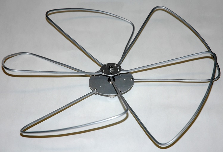
Photo 1
The new version of the
Horizontally
Polarised Omnidirectional (HPOD) antenna also known as a Clover Leaf
antenna.
Photo 2
The original version of the
Clover Leaf
antenna as installed at the VK6RTU beacon at Kalgoorlie.
The
current version of the antenna is based on all dimensions determined
for the first version and is primarily interested in an achieving
superior physical construction techniques and carry out more detail
performance measurements. The antenna will be installed and reviewed
for satellite and ISS communication.
Antenna
details
Frequency:
420
to 450MHz
Wavelength:
690
mm
VSWR:
Better than 2:1 between 425MHz and 445MHz
Polarization:
Horizontal
Gain:
Neutral gain compared to a dipole at 0 dBd (approximately).Less than
-17dBd compared to a cross polarized dipole
Construction
The antenna is constructed around a standard male N connector with a
100mm diameter aluminium radial mounting disk with a 16mm centre hole
to attach to the N connector with the standard coax gland
screw cap as shown inPhotos 5 and 6.
The elements have been attached with 3mm diameter pop-rivets to the
mounting disks.
Photo
5.
Shows 6mm Stainless Steel stud and N connector pin assembly
Photo
6.
Main attachment hub
Photo
7.
Shows petal element hub attachment with 3mm pop rivits.
The
smaller upper disk is fitted to a standard male N connector's coax
centre pin with a 6mm diameter stainless steel stud and positioned in
the N connector and secured with two part epoxy. A small rubber
grommet has been fashioned to fit tightly in the end of the N
connector body with a smearing of marine grade silicon to make to
assembly water proof.
The antenna mounting is a standard antenna mirror mount bracket with a
female to female N connector bulkhead socket fitted for a range of
similar antennas that are constructed around male N connectors. See: Generic
Antenna Mount.
Antenna
testing
Testing
was completed using a NanoVNA for all antenna range measurements
including both SWR and antenna gain performance.
The
SWR measurements showed a very broadband match with an SWR of less
than 3:1 from approximately 410MHz to 490MHz and very good match at
the target frequency of 438MHz.
The
Smith Chart display indicates that the antenna is resonant at 459MHz.
This result is consistent with the antenna in the paper and the Mk 1
version of the Clover Leaf antenna.
Photo
10.
NanoVNA display of an SWR of less than 3:1 from approximately 410MHz
to 490MHz.
Photo
11.
NanoVNA display of an SWR of less than 2:1 from approximately 430MHz
to 445MHz and very good match at the target frequency of 438MHz of
1.33:1.
Photo
12.
Shows the Smith Chart display that indicates the antenna’s resonant
frequency is around 458MHz.
Antenna
Gain Range Testing
This
is the most important antenna measurement because even if all other
measurements such as SWR and resonance are satisfactory, however if
the antenna fails to achieve at least an approximation of the desired
or predicted gain, it can be considered a failure. Measuring antenna
gain is perhaps one of the most challenging tasks to accomplish
successfully, as it requires a large and unobstructed area, especially
free from metallic obstacles that can significantly distort the
antenna's ideal radiation pattern. Figure 4 below illustrates an
example of an antenna gain range test using the NanoVNA.
Figure 4 Shows
the basic antenna gain range test set-up.
Figure
4shows
the basic set up with d indicating
the distance between the Source dipole antenna and the Reference
dipole antenna and while not critical needs to be between 2 and 3
wavelengths apart. In the set up the two antennas were placed
2mtr (approximately 3 wavelengths) apart.
The
ideal separation for antenna gain testing depends on various factors
such as the frequency of operation, the type of antennas being tested,
and the testing environment. Generally, a separation of at least 2-3
wavelengths is recommended between the transmitting and receiving
antennas to minimize interference and achieve accurate measurements.
Larger antenna separations can give false readings due to ground
reflection and other multi-path effects.
The
distance (d) between the source distances to the antenna under test
(435MHz Yagi antenna) is taken from the source dipole to the Yagi's
driven element.
The
suitable height above ground for antenna gain testing depends on
various factors, including the type of antenna, the desired testing
accuracy, the operating frequency, and the testing environment. As a
general guideline, a height of at least 1 to 2 wavelengths above
ground is recommended to minimize ground effects and reflections.
The
antennas in this set-up are positioned 1.5 meters above the ground,
which is slightly over 2 wavelengths at 435 MHz.
Measurements
with horizontal polarization are less affected by ground bounce and
can provide more accurate and consistent gain values. Horizontal
polarization also helps simulate more ideal free-space conditions,
which is important for accurate gain characterization.
Source
Antenna is
a 435MHz Source dipole antenna.
Reference
Antenna is
also a 435MHz Reference dipole antenna. A measurement will be taken
with this antenna to determine the base line. This antenna is replaced
with the Clover Leaf antenna and the return loss measured that will
show the gain in dB with respect to the Reference dipole antenna.
NanoVNA set
to LOGMAG with a display of typically -2.5 ~ +2.5dB and
calibrated to remove the lead characteristics from the measurements
and with the reference antenna and set the base line to 0 as per Fig
4.
Photo
12 NanoVNA
showing the Fig 4 set-up and calibrated for the base line to be zero.
Figure 5 Shows
the basic antenna gain range test set-up with the antenna under test
in place.
Target
performance.
It
is generally expected that a properly constructed Clover Leaf antenna
can typically exhibit an approximately neutral gain to slightly
positive against a dipole.
Test
Results.
The
test results recorded a slight return gain (0.86dBd) for the Clover
Leaf antenna compared to the 435MHz Reference dipole antenna. This
gain is defined as neutral dBd for the Clover Leaf antenna.
Considering that a dipole antenna in free space has a gain of 2.15 dB
over the theoretical isotropic antenna, the 6-element Yagi
demonstrates an approximate gain of 2.15 dBi. This gain closely
matches the expected gain results for this antenna.
Photo
11 NanoVNA
showing the Fig 5 set-up and displaying Clover Leaf antenna's gain
compared with the reference dipole antenna.
The
source dipole was then rotated to a vertical position to measure cross
polarized gain with a more or less expected measurements indicate
negative gain of – 17 to 18dBd.
Photo
12 NanoVNA
showing the Fig 5 set-up and displaying Clover Leaf antenna's gain
compared with the reference dipole antenna with the source antenna in
the vertical cross polarized position. Result measurements indicate
negative gain of –17 to 18dBd.
Conclusion.
The Mk 2 Clover Leaf
antenna, designed for the 70cm band (420 to 450 MHz), is a
horizontally polarized antenna suitable for SSB and beacon use. It has
a neutral gain of 0 dBd compared to a dipole of the same frequency and
polarization. This antenna is very broadband and, although complex to
construct, produces consistent and replicable performance results.
Photo 13 The
Horizontally
Polarised Omnidirectional (HPOD) antenna also known as a Clover Leaf
antenna installed.
Video
of the construction and testing of the 435MHz Clover Leaf Antenna.
Establishment of a Beam Wireless Service, providing the longest and fastest telegraphic communications in the world. The first such communication between Australia and England was in January 1927.
Notice Board
VK6YSF JS8Call and
Olivia 8/250 operations.
Current activity is generally
focused - though not restricted to - JS8Call operations on the 20,
30m, and 40m bands.
Olivia 8/250 is used occasionally on the 20m band.
Proposed
band and mode activity
is often communicated on HamSpots: https://hamspots.net/js8/
or my profile on
Repeaters Page Updated
- Expanded and refreshed information on VHF and UHF repeaters across Western Australia's Central Coast, Perth, the Avon Valley, and the Peel region. New AllStar Link information has also been added, including linked repeater details and
gateway information across the State.