|
435MHz
1/4λ GROUND PLANE ANTENNA
435MHz
1/4λ
ground plane tower mounted antenna. Install
July 2011
With the view of
doing satellite operations with a simple non-steerable antenna a
number of antenna designs are being reviewed and many of them will
be revisited in search for the optimum simple satellite ground station
configuration. The vision at this stage is to use the Kenwood TS-736R
transceiver with a short 5mtr run of LMR400 low loss coax to a
suitable mast head amplifier and antenna. Signals will be weak as a
non-steerable antenna will ideally have general hole of sky view with
the result of little gain in any particular direction and therefore a
quality mast head amplifier is likely to be a necessity if this system
is to work. With the transceiver in place and the LMR400 coax run to
the top of a small sub-mast mounted on the roof directly above the
radio position the antenna is to be the next issue to be dealt with
leaving the mast head amplifier to last.
The antenna is to be
regarded at this stage at least as being very experimental with the
intention to trial a number of designs for comparison.
With this in mind a generic antenna mount has been installed on
mast to allow for easy replacement of trial antennas.
The antenna mounting
is a standard antenna mirror mount bracket with a female to
female N connector bulkhead socket fitted and all experimental antennas
are to be constructed around male N connectors. This arrangement
should be suitable for simple antennas such as 1/4 wave ground plane
from frequencies as low as 50MHz to more complex collinear antennas in
low GHz bands and represents a convenient test bed for trialling
various antenna development not all necessarily for satellite
operations. See: Generic
Antenna Mount.
The first antenna to
be constructed as it has potential as a satellite up and down link
antenna is a 1/4 wave ground plane centred on 435MHz.
The 1/4 wave ground
plane or monopole antenna in this instance will be mounted on a mast
and therefore a perfect ground pane will not be present. The ground
pane will be simulated as is normally the case with a number of
metallic elements extending out horizontally from the base of the
monopole element and connected to the shield of the coax. The ground
plane elements number at least three, but preferable more, typically
four and this case six. The length of the ground plane elements are
approximately 5 -10% longer than the radiating element, but can be
longer. My copy of the RSGB VHF UHF Manual by G. R. Jessop, G6JP
suggests element lengths of 0.28λ to 0.30λ
The 1/4λ vertical
Radiating Element (A) = 300/f x 0.25 x 0.95. The Radial Elements (B) =
300/f x 0.25 x 1.0 or about 5% longer than the radiating element less
mounting hardware and is angled at approximately 45° angle in order
to create a load impedance of approximately 50Ω
|
Frequency
(MHz)
|
A
(Radiating Element) mm
|
B
(Radial Elements) mm
|
|
52.50
|
1357
|
1429
|
|
70.25
|
1014
|
1121
|
|
146.50
|
486
|
512
|
|
222.00
|
321
|
355
|
|
435.00
|
164
|
172
|
Table of 1/4 Ground
Plan element dimensions for various local Australian and some
international amateur radio bands.
Construction
Constructed around a
standard male N connector and a 60mm diameter aluminium radial mounting
disk with a 15mm centre hole for attachment to the N connector with the
standard coax gland screw cap. The radial elements have been attached
with 2mm diameter pop-rivets and angled down at 45 deg approximately
25mm out from the disc edge. Bending the elements too close to the
pop-rivets holes may cause the aluminium tube to break at the section
weaken by the hole.
The radiating element
is fitted to a standard male N connector's coax centre pin and
positioned in the N connector and secured with two part epoxy. A small
rubber grommet has been fashioned to fit tightly in the end of the N
connector body with a smearing of silicon to make to assembly water
proof.
While not an
essential consideration for frequencies of less than about 440 MHz an
attempt was made to maintain a continuation of the 50 ohm line
impedance to the point where the radiating element exists the N
connector body by fitting a 4mm external diameter sleeve over the
radiating element with in the body of the N connector. The below
calculation indicates that the nominal 50 ohm line impedance will be
maintained to the base of the antenna proper
Based on the inside
diameter of the N connector body being approximately 9mm and the
outside diameter of the sleeve being 4mm a result of a 49 Ω
line impedance a very close continuation of the feed line impedance.


Fig
1
435MHz
1/4λ ground plane
radial element mounting
plate.

Fig
2
435MHz
1/4λ ground plane
radial element assembled.

Fig 3
Complete 435MHz
1/4λ
ground plane
assembly

|
|
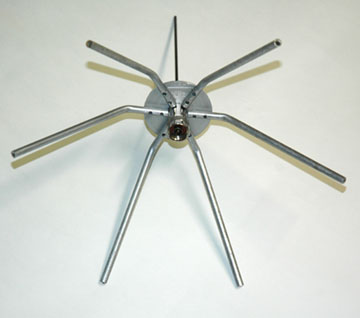
| Photo 1
435MHz
1/4λ ground plane
assembled - Top view |
Photo 2
435MHz
1/4λ ground plane
assembled - Bottom view |
Fig 4
435MHz
1/4λ ground plane
SWR
Details
of the generic antenna mount. See: Generic Antenna
Mount.
TOP
OF PAGE
Page
last revised 12 March 2022
|