|
20m BAND (14MHz) 1/4 GROUND PLANE ANTENNA
14MHz
1/4 portable ground plane antenna. September 2015.
The portable 20m ground plan antenna is
a basic wire arrangement with a wire radiator and three radials spaced
120 degrees apart. The radiator and radials are fed at 50ohms via a 1:1
current balun. The radiator and radials all have attachment loops
at the ends so that the antenna can be hung in a tree or from a Squid
pole with the radials pegged out with ropes and tent pegs.
The ground pane
will be simulated as is normally the case with a number of metallic elements extending out horizontally from the base of the monopole element and connected to the shield of the
coax or in this case via a 1:1 current balun. The ground plane elements number
three in this design and the length of the ground plane elements are approximately 5 -10% longer than the radiating element, but can be longer. The RSGB VHF UHF Manual by G. R.
Jessop, G6JP suggests element lengths of 0.28λ to 0.30λ
As the name suggests the 1/4 wave ground plane
has elements that are a 1/4 of a wave length of the operating frequency in length, this however is the electrical length not the physical length. The physical length is reduced due to the effects of the diameter of the elements; the reduction is referred to as the ‘K’ factor which is typically a figure of about 0.92 to 0.98, this figure is then multiplied by the electrical wave length to give the resultant physical length.
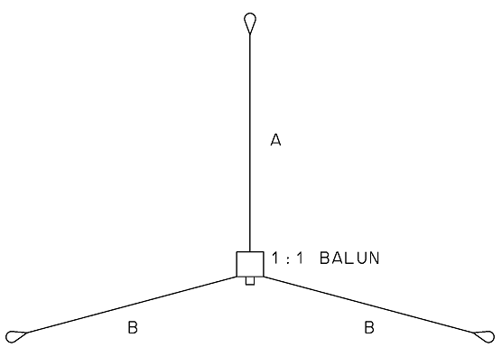
The below calculation determines the physical length of the radiating element ‘A’ and the
three radial elements ‘B’.
The 'B' elements are as discussed earlier to be about 10% longer,
therefore the formula for the 'B' elements has a 1.1 multiplier.


Frequency = Frequency in MHz,
el = The length of the antenna element. A 1/4 wave element will be presented as 0.25 for example.
K = K factor referred to in the below
calculation and chart.
The
result value for the above calculations would be in metre, but has
been presented in mm as more convenient value in the practical
approach to this calculation the result in metres would be multiplied
by 1000 to present millimetres.
The elements are all electrical quarter wavelengths not physical lengths, with the physical length being slightly shorter. The basic wavelength calculation is multiplied by a factor of ‘K’. Typically K is a value between 0.92 and 098 and is mainly dependant on the ratio of the wavelength and the diameter of the wire or rod used. The K factor can be derived from the below
Figure 2 Chart and the below simple formula. In this case the
0.5mm wire element at frequency of 14.15MHz results in a ration of
20000 or 20k which is referred
up from the bottom of the 'K' factor chart to the curve and then referred
across to the multiplying factor which in this case was determined as approximately
0.97.

HWCD_Ratio = Half Wavelength to Conductor Diameter Ration.
Half_Wavelength = The half wavelength of the 20m band being
obviously about 10000mm (10m).
Cond_Dia = The diameter of the copper wire conductor used in the
antenna in mm. In this case 0.5mm

Figure 2
'K' Factor chart that determines the element multiplier factor based on the ratio of the diameter of the conductor diameter to a half wave length.
A spreadsheet with element length formula has been presented in the below table indicating the ideal lengths for the radiating and radial elements for various
amateur radio bands that this configuration would be practical.
All spreadsheet calculations have assumed a 'K' factor of 0.97 which
is likely to be different given the different wavelengths and wire diameter
that may be employed for a practical antenna. In the real world it is
alway wise to allow a bit extra length and prune to get the best
results and as mentioned earlier the 'B' radials can be a bit longer
with out having any detrimental effect on matching, leaving only the
'A' radiator to be experimentally trimmed.
|
Frequency
(MHz)
|
A
(Radiating Element)
|
B
(Radial Elements)
|
|
metres
|
inches
|
metres
|
inches
|
|
7.10
|
10.246
|
403.40
|
11.620
|
457.47
|
|
10.15
|
7.167
|
282.18
|
8.128
|
320.00
|
|
14.18
|
5.130
|
201.99
|
5.818
|
229.06
|
|
18.10
|
4.019
|
158.24
|
4.558
|
179.45
|
|
21.20
|
3.432
|
135.10
|
3.892
|
153.21
|
|
24.95
|
2.916
|
114.80
|
3.307
|
130.18
|
|
28.60
|
2.544
|
100.15
|
2.885
|
113.57
|
Figure 3 Table of
1/4λ Ground Plan element dimensions for various
amateur radio bands.
Construction
The
1:1 Guanella current balun is the convenient central hub of the
wire ground plane antenna and while the balun was never designed with
this antenna configuration in mind it works fairly well. Ideally the
two binding post would be better suited with one at the top and the
other at the bottom and SO239 coax connector to the side, however you
work with what you have. The above dimension calculations are based on
VHF and UHF ground plan antennas and while that will work and produce
a 50ohm match it will only achieve that when the radials angled down
at about 40 degrees and the antenna is high above the ground, when the
radials not angled down and are more or less flat due to
practicalities of attaching the antenna to a Squid pole for example
and the antenna is only about 2m from the ground the impedance will be
much lower than the ideal 50ohms. A simple solution is the prune the
radiator until the best match is achieved and this is likely to be of
the order of 4.6m, significantly shorter than the calculations would
suggest. If the antenna was hung higher in a tree for example and the
radials could be angled down at the more ideal 45degrees then the
radiator would need to be closer to the 5.13m length.
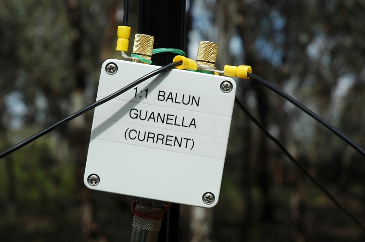
Photo
1 Shown is the 1:1 Guanella current
balun, the central hub of the
wire ground plane antenna. The radiator wire element is attached to
the left post and the three radiators are attached to the right
binding post.
|
|

|
|
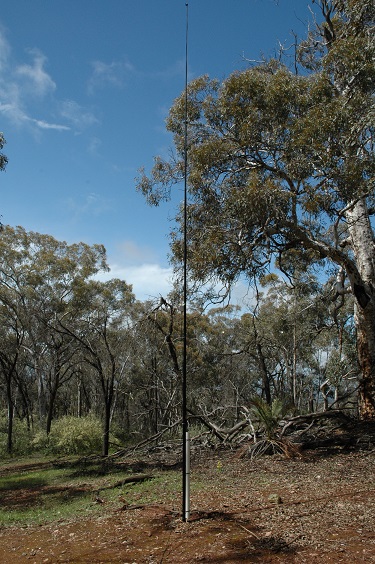
Photo 2 Squid pole
assembled in the field
|
Photo 3
Squid pole mounting arrangement.
|
Testing
With the antenna assembled and erected
clear of surrounding metallic
objects, the antenna was connected to an AIM 4170C antenna analyser to
ascertain how the antenna loaded up.
The goal here is match the antenna at
about the centre of the 20m band (14.0 - 14.35MHz) and being close to the resonant
frequency and achieving best possible impedance match resulting in an SWR of
about 1.5 - 1 or less.
The AIM 4170C produces a display of all
relevant data and most importantly it can project it's analysis to
the antenna end of the coax giving a truer picture of the antenna.
Finally with the most modest
trimming of the radiating element the required parameters were
realised with a resonant frequency of 14.236MHz and a SWR of 1.103 at
14.19 MHz.

Figure
4 AIM
4170C antenna analyser of the antenna mounted to a Squid pole and the
feed point being approximately 2m above the ground.
AIM
4170C antenna analyser explanation;
|
SWR
|
Standing
Wave Ratio.
|
|
Zmag
|
Total
Impedance.
|
|
Theta
|
Phase
angle between voltage and current.
|
Figure 4 indicates that the antenna's SWR is blow 1.5:1 over the
entire 20m band (14.0 - 14.35MHz). This measurement was taken with the
antenna attached to a 7m Squid pole and therefore the antenna was only
about 1m above the actual ground. It would be expected that the
results would differ when install at greater height, however an expectable
SWR would be maintained.
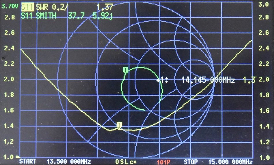
Figure
5 NanoVNA
measurements of the antenna mounted to a Squid pole and the
feed point being approximately 2m above the ground.

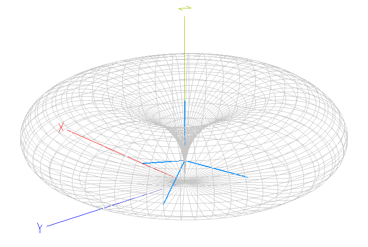
Figure
6 MMANA
antenna model
indicating uniform low angle radiation pattern.
Figure
7 MMANA antenna
model
showing an ideal flat donut pattern that will be suitable for long
distance communication.
Operational
notes
The
20m band ground plane antenna while designed for the 20m band has
proven useful on the 15m, 17m 30m and 40m bands when used with an ATU. Operating
on bands other than the 20m band it is important to keep the feed
line coax as short as practical to reduce losses on the coax cable.
References
ARRL
Antenna Book 18th Addition
.
Balun
used for is this configuration is a 1:1
Guanella
Current
balun
using a
L15 ferrite core (1.8 -
30MHz). BALUN
1:1 CURRENT
TOP
OF PAGE
Page initiated 25 September, 2015
Page
last revised 12 March 2022
|